enrico
Member level 3
Dear All,
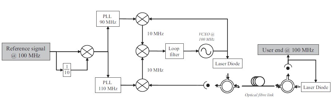
I am facing difficulties to understand the impact of the delay caused by the round trip of fiber optical link at the figure below and would appreciate your feedback :
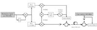
1. Since we have 90 + 110 MHz signals (and few other low spurs) at the output of the mixer which is at left side of figure, why do we need the PLL's of 90 and 110 MHz since we could replace it by in e.g. SAW band-pass filters with 1 MHz Bw only (of-the-shelf) ?
2. If I suppose an optical link of 100Km, the round trip of signal I expect to get is around 500.08 uS of time delay (5uS delay @ Km + 80 nS E/O photodiode/laser conjunct). This will affect the loop bandwidth of the loop filter in the picture. Does it means I will need a very small Loop Bw in e.g. 2 KHz ? I only found the relationship of loop bandwidth with settling time, SSB phase-noise and other unrelated parameters, and I thought the reason why the PLL's are necessary is because they are acting as active filters to suppress spurs.
3. Since we expect to have both 10 MHz signals arriving at the mixer at center of figure, thefore resulting in only in phase difference between the signals. We can conclude that the branch of the fiber optical link to have a considerable phase delay. If in case that mixer can be replaced by a phase-frequency detector, and a frequency detector can detect max. 2*PI between diff. phases, how can it cope with a huge delay that in fact represents angular phase that surpass 2*PIrad ?
4. What it is necessary to pay attention on this design ? I mean with regards to the definition of loop bandwidth and consequently adopted active low pass filter before the VCO and its values.
Thank you, E.
I am facing difficulties to understand the impact of the delay caused by the round trip of fiber optical link at the figure below and would appreciate your feedback :
1. Since we have 90 + 110 MHz signals (and few other low spurs) at the output of the mixer which is at left side of figure, why do we need the PLL's of 90 and 110 MHz since we could replace it by in e.g. SAW band-pass filters with 1 MHz Bw only (of-the-shelf) ?
2. If I suppose an optical link of 100Km, the round trip of signal I expect to get is around 500.08 uS of time delay (5uS delay @ Km + 80 nS E/O photodiode/laser conjunct). This will affect the loop bandwidth of the loop filter in the picture. Does it means I will need a very small Loop Bw in e.g. 2 KHz ? I only found the relationship of loop bandwidth with settling time, SSB phase-noise and other unrelated parameters, and I thought the reason why the PLL's are necessary is because they are acting as active filters to suppress spurs.
3. Since we expect to have both 10 MHz signals arriving at the mixer at center of figure, thefore resulting in only in phase difference between the signals. We can conclude that the branch of the fiber optical link to have a considerable phase delay. If in case that mixer can be replaced by a phase-frequency detector, and a frequency detector can detect max. 2*PI between diff. phases, how can it cope with a huge delay that in fact represents angular phase that surpass 2*PIrad ?
4. What it is necessary to pay attention on this design ? I mean with regards to the definition of loop bandwidth and consequently adopted active low pass filter before the VCO and its values.
Thank you, E.
Last edited: