Continue to Site

Welcome to EDAboard.com

Welcome to our site! EDAboard.com is an international Electronics Discussion Forum focused on EDA software, circuits, schematics, books, theory, papers, asic, pld, 8051, DSP, Network, RF, Analog Design, PCB, Service Manuals... and a whole lot more! To participate you need to register. Registration is free. Click here to register now.

[SOLVED] PIC programmer problem (using programmer simmilar to Olimex PIC-PG2 (JDM style))

Status
Not open for further replies.

ghormoon

Newbie level 4
Joined
Mar 15, 2011
Messages
7
Helped
0
Reputation
0
Reaction score
0
Trophy points
1,281
Location
Koprivnice, Czech Republic
Activity points
1,341
Hello,
I've been searching for a solution for almost a week, most results were form this forum, but I haven't managed to make it working.
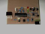
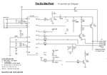
I've built programmer according to this scheme: https://www.bravekit.com/document/PIC_JDM/PIC_JDM_schem.pdf
It should be able to program PIC18F4550 which i have.
I've tried few softwares, eg. in PICPgm it detects the programmer (as JDM), but doesn't detect the PIC (doesn't matter if I set it to Olimex PIC-PG2 manually).
I thought that it may be caused by low voltage, but I haven't been succesfull even with adding 12V and 5V external power supplies instead of powering from serial port. (When I measure serial port without programmer, it gives around 11.6V, when I connect programmer then about 10.5V and when i connect PIC to the programmer, something above 9V, if I measure the ICSP connector, i get about 5V without PIC, 1.5V with PIC (without external supply))
Any ideas?
Thanks in advance,
Ghormoon


Hi,

As you might have seen in this forum, JDMs work for some people, some do not !
Some suggest even the Pcs serial port can make the difference.

You might find the PicAll Parallel programmer a more reliable option, though once you can program a 4550 / 2550 then build yourself a Pickit2 clone if you are going to program pics frequently.
 

Attachments

  • Pic Parallel Programmer.pdf
    322.2 KB · Views: 165
I've got one friend who may borrow me lpt programmer, it looks simmilar, but not same, only problem is that he says it requires 16-30VDC, so I'll have to borrow power supply somewhere :D
**broken link removed**

I'd like to build pickit clone later (I don't have 18f2550 now and I'm not sure if I'm able to port it to 18f4550)
But there are too many versions ... this one should be able to program and debug both 3.3 and 5v pics ... has anyone tried it?
Untitled.JPG (image)
 

I've got one friend who may borrow me lpt programmer, it looks simmilar, but not same, only problem is that he says it requires 16-30VDC, so I'll have to borrow power supply somewhere :D
[

Yes that looks almost identical and should work ok, providing you follow those points in that pdf.
Just use two 9v batteries in series, it takes very little current.

I'd like to build pickit clone later (I don't have 18f2550 now and I'm not sure if I'm able to port it to 18f4550)
But there are too many versions ... this one should be able to program and debug both 3.3 and 5v pics ... has anyone tried it?

The Microchip PK2 software for the 2550 does program straight into the 4550 without any recompling and it works fine as a PK2, have done it myself.


Have not built from that design, though it does include the variable VDD circuitry, which is a good feature.

If you want to keep things simple, this is as basic as you can get, though you can still program 3v3 chips as well, as again I have done.
Simply power the whole PK2 circuit at 3v3 or power the target chip with 3v3 before applying 5v power to the PK2.
 

Attachments

  • pk2mini.jpg
    pk2mini.jpg
    75 KB · Views: 132
  • minipk2.jpg
    minipk2.jpg
    66.5 KB · Views: 158
Does this power at least the 5v chips? or you have to power the circuit from external supply all the time? the one I've linked schould power the programmed chip from usb ... or do I understand it wrong and you power it different way (I don't see any connector to power whole pickit)?
 

Hi,

Both version of Pk2 are self powered from the USB cable as are the target chips.

Looking at Sarins circuit the top section is virtually the same as mine, though he has used a transistor Q5 for my diode D1.

If you built it as my diagram, it is self powered and programs 5v chips.

When you want to program 3v3 chips then think the best thing would be to add in Sarins voltage adjuster circuit, plus extra diodes D4/5/6 and resistors around the iscpCLK and DAT lines.
Its straight forwards and low cost, its hardly worth messing doing it other ways imho.

Edit -
Just to re-iterate an often overlooked regular comment about building you own programmer and all the trial and trivulations involved - its so much easier and probably cheaper to buy a genuine Microchip PK2 - I did and its one of my 'best buys' - I just built the clone as backup / challenge.
 
Well, I'll try the Sarins schem then, I'd like to try out more PICs later, not only 18f4550, so it would be better to have it more "universal". I'm trying to redraw the Sarins schem to the "old style" one where everything is connected, not just "linked by names of lines", but it gets quite messy ^^ I'm not good at schematics.
Btw, as far as I know, pic18f4550 has some "28pin simulation mode", that may be that you've talked about, should I connect it like the 18f2550 (14 first and 14 last pins) or to the pins with same name?
Later I'll post the result of redrawing, dunno how long it will take (I don't have to hurry, my friend with the working programmer lives 400km away...), hopefully I won't screw it up ^^
 

Hi,

You want to download the PK2 User Guide https://ww1.microchip.com/downloads/en/DeviceDoc/51553E.pdf
It tells you all about the extra features like USART Tools and Logic Analyzer plus there are full circuits at the back.

pic18f4550 has some "28pin simulation mode"

Thats a new one on me, not saying its not true but never heard of it.
When drawing the 4550 diagram use the same PORT Pin Labels eg RA0, RC1 not the pin numbers.

There are quiet a few free / trialware design programs such as Eagle that might make drawing your circuit easier.
 
I know that original pickit has more features, but I don't think I need them now, at least it's not worth the cost for full pickit (even clone) ... I'm just a student and I can't afford spending that much. So I'll build "reduced" pickit clone to have the programmer+debugger function, that should be enough for starting with PICs I hope.
Originally I wanted to build just the JDM programmer, which doesn't work ^^ But anyway, I'd later have to build pickit or something, because I'd like to try out some 24F and 32F PICs.
 

Thanks, anyway, I'll try out paraller programmer for now and build pickit later (I think that the serial programmer doesn't work because of the low voltage on comport).
I'll mark it as solved for now, so people won't waste time here, thanks guys, and don't worry, I'll be back with other problems ^^ :D
 

Status
Not open for further replies.

Part and Inventory Search

Welcome to EDABoard.com

Sponsor

Back
Top