Continue to Site

Welcome to EDAboard.com

Welcome to our site! EDAboard.com is an international Electronics Discussion Forum focused on EDA software, circuits, schematics, books, theory, papers, asic, pld, 8051, DSP, Network, RF, Analog Design, PCB, Service Manuals... and a whole lot more! To participate you need to register. Registration is free. Click here to register now.

BATTERY BACKUP and Trickle Charge

Status
Not open for further replies.

angryboy

Newbie level 4
Joined
Mar 15, 2011
Messages
6
Helped
0
Reputation
0
Reaction score
0
Trophy points
1,281
Activity points
1,358


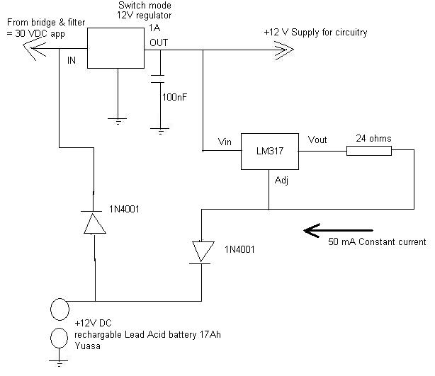
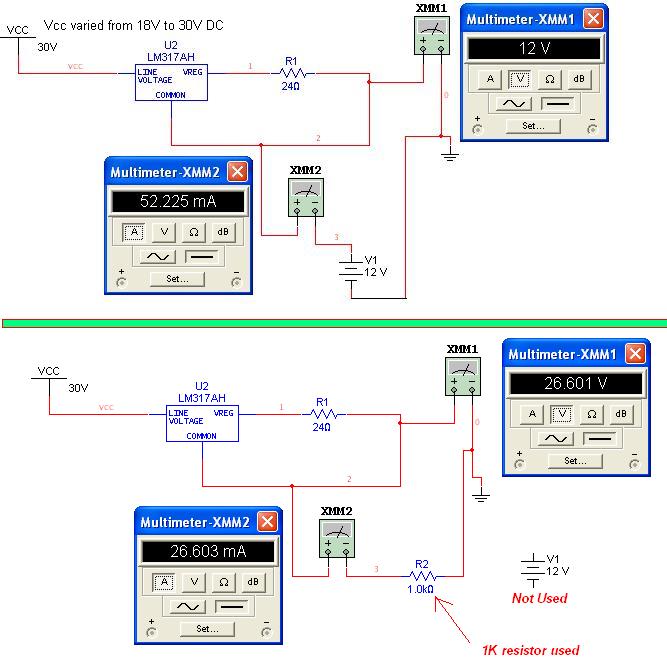
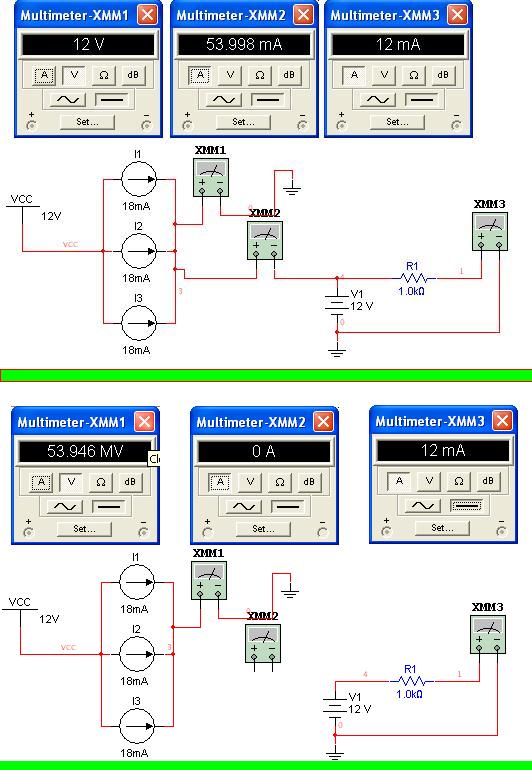
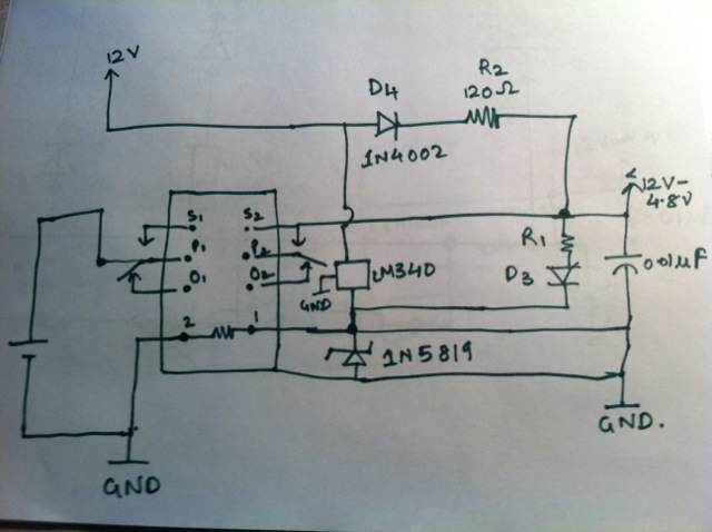
I am trying to use a 12V DC battery 17Ah Lead Acid from Yuasa with an existing mains operated circuitry. I have attached the circuit diagram that I am trying to implement. Circuit would be operated using mains under normal condition while backup battery is still connected. When operating on mains, back-up battery would receive 50mA constant current charge using LM317 (circuit obtained from LM317 datasheet). In case of mains failure, backup battery kicks-in. Are there any limitations or potential hazards with this circuitry. Would a 1/4Watt 24 ohms resistor enough for this circuit? Please advise!
 

the charger circuit based on lm317 can be moved towards the mains dc side.
50ma for a 17ah battery is too small.
 
I agreed with srizbf. You can move the backup battery charging circuit (LM317)to the 30V input. Is there a reason you choose to keep the LM317 at the output of the 12V DC-DC converter?

In case you choose to keep your circuit as is, here are a few things to consider. There are too much voltage drop from LM317 and 1N4001. The LM317 specified 1.5V dropout at 20mA and about 0.7V drop for the diode. So your it would very very long time for your Yuasa to be charged to 12V.

You also have a 1N4001 from Yuasa to 12V DC-DC converter input. So there is another 0.7V drop. You might want to check with the 12V DC-DC converter manufacture to see if it can operate in 100% duty cycle.

Finally as srizbf pointed out, 50mA charging a 17Ah battery would take about 14 days to fully charged.

When you finally built your circuit, you can test your backup battery charger with a battery simulator. Instead of wait for 14 days to test your backup battery charger circuit, you can use a battery simuator to speed up the test. I found this battery simulator you can use (click on the link).

Have fun.
 

Very Comprehensive information. Yes I can connect LM317 input directly to the output of bridge & filter. 14 days is OK as Yuasa would not be used frequently say three times a year for few hours. The question is can this be connected to Yuasa for indefinite period of time without damaging it? 12V switch mode reg can take input from 9V to 32V, so adding a diode would not make a difference. Now, this is where my limitation is with knowledge about battery charging: I tried simulating the circuit in Electronics workbench (See attached diagram) Vcc was varied from 18V to 30V but output voltage and current readings were constant i.e., 12V and 52mA respectively hence proving the contant current phenomenon. But, when I connected a 1K-ohm resistor at the output instead of 12V battery (rechargeable), output voltage and current started varying when input voltage was varied from 18-30V. Also, changing the load resistor from 1K-ohm to higher or lower values resluted in change at output voltage and current. Can't get my head around this problem as output current should still be 52mA if LM317 is configured as constant current source. Please advise
 

I quickly looked at Yuasa website. It looks like the battery you are using is lead-acid. I am more familar with lithium ion battery than lead-acid. My recollection is that there should be no damge to battery, but you should check with Yuasa.

I understand what happen in your circuit. When you replaced the battery with a 1k-ohm resistor, the circuit is trying to source 52mA into the 1k-ohm. 52mA into 1k-ohm is 52V. But the input is only 30V, so the LM317 is in dropout (saturated). If you put a 100ohm resistor, you should get 5.2V. Any resistor less than 500ohm should get you constant 52mA current. The conclusion is your circuit is working.

I recommend you use a battery simulator for testing instead of a resistor. If you don't have a battery simuator, you can use one of the two:

1) a two-quadrant power supply (some time call bipolar supply). Or a four-quadrant power supply.
2) Use a regular variable power supply with a power resistor load at the output. This resistor will sink the current from LM317.
The resistor value should be choosen so that there always at least 60mA current. For example, if you are planning to test your battery voltage down to 5V, the resistor value should be ~80 ohm.

---------- Post added at 10:06 ---------- Previous post was at 09:38 ----------

Angryboy, I forgot one important point. You need to limit the maximum charging voltage to ~12V, otherwise it will damage your battery. Your new circuit (LM317 at the 30V input) does not have that limit. Your old circuit (LM317 at DC converter output) does, but the maximum voltage is too low.

So the easiest solution is to use **broken link removed** from Central Semiconductor instead of LM317. You can use three CMJH180 in parallel to get about 54mA current. The anode of the these diodes are connected to the +12V DC-DC output and the cathode are connected to the battery plus terminal. That should work.
 
  • Like
Reactions: angryboy

    V

    Points: 2
    Helpful Answer Positive Rating

    angryboy

    Points: 2
    Helpful Answer Positive Rating
The normal, and usually recommended way, of chargung a lead acid battery is from a constant voltage source. If you use a constant current source you run the very real risk of overcharging it.

The value of the voltage source is usually equal to the fully charged voltage of the battery. When it is first connected, the battery voltage being rather low, the charging current will be a certain value. As the battery's charge accumulates, its voltage rises, and as a result the current slowly diminishes.
Once the battery's voltage is equal to that of the charging source, the current tends to zero.
 

    V

    Points: 2
    Helpful Answer Positive Rating

Very helpful. @kcyang: When you say to limit the maximum charge voltage to 12V, I simulated the circuit by removing the rechargable battery, the output voltage measured in this case was about 0.5V less than input such as 17.5 at output for 18V input of LM317, this means that when I first connect the battery it would see that higher value of voltage that could damage the battery, please correct me if I am wrong.
@kcyang and syncopator: If I use 3 current limiting diodes in parallel at the output of DC-DC switch mode regulator (used in my very first post) and remove the LM317 then, offcourse the current would stay at apprx.54mA, but would I need any series resistor and would there be any voltage drop across current limiting diodes. If there is a voltage drop then would that not affect the charging voltage. I tried simulating the concept using 3 constant dc current sources 18mA each in parallel and got 12V at output when battery(rechargable) is connected and about 50mV when no battery is connected at the output, would it be the same case when I connect CMJH180 in parallel? Please advise!
 

Angryboy, For your first question, when you connect the battery and turn on your circuit, the voltage across the battery is dictated by the initial battery voltage (not ~18V). For example, if the initial battery voltage is 10V, after you apply input voltage, the battery voltage stays at ~10V. At this point, the LM317 will source 52mA into the battery. The battery voltage starts to rise slowly. After two weeks the battery voltage reaches about 12V (Full). After that the battery voltage continue to rise beyond 12V and potential go to ~18V. Lead acid battery can charge to about 14V, higher than 14V will potential damage it.

For your second question, you don't need any series resistor. The current limiting diode take cares all of that for you. The voltage drop across the diode will be difference between the 12V and the battery voltage. As the battery is being charged, its voltage will rise and the difference voltage will narrow. As the battery voltage is approaching 12V, the charging current decreases, which is good because your battery is getting full. For example, when you battery is at 11V, the difference voltage is 1V and the current reduces to about 18mA (using data from the datasheet). When the battery voltage reaches about 11.5V, the current reduces to 10mA. And so on. Your battery will envenually reach near 12V. This is very tyipcal of CC/CV charger.

For your simulation, you need to add a real diode (1N4001 is close enough) in series with each current source. Current limiting diode equivalent circuit is a diode in series with a current source.

For you simulation, you should check the charging current vs battery voltage (0V to 13V). You don't need to check the case where battery is remove. If the battery is removed (open), the voltage should be 12V.
 

    V

    Points: 2
    Helpful Answer Positive Rating
angryboy I hadn't looked closely at your first circuit before.

I have now done so. It won't work. Look at this and see how the voltages for charging the battery sum up.


battch.gif
 
  • Like
Reactions: angryboy and kcyang

    kcyang

    Points: 2
    Helpful Answer Positive Rating
    V

    Points: 2
    Helpful Answer Positive Rating

    angryboy

    Points: 2
    Helpful Answer Positive Rating
@syncopator: does this mean that a minimum of 18.7V (Which obviously wont be the output of 12V reg) is required at the input of LM317 to work? If this is the case then offcourse this circuit wont work as you suggested.
@kcyang: If I connect 3 CMJH180 diodes in parallel at the output of 12V reg without any resistors and then connect the battery via diode to the input of same 12V reg (which is also connected to output of bridge & rectifier appr. 20-30V DC) then would this solve all the problem? Secondly if I want to use the same setup with three diodes in parallel (52mA) at output of 12V reg for another circuitry that is using nine 1.2V batteries in series (10.8V) 2000mAH NiMH
(Duracell | Batteries | Rechargeable Batteries | AA Rechargeable Batteries | NiMH Rechargeable Consumer Style Batteries & Chargers |5000394203853)
Would there be any adjustments required in the circuitry? Again this battery would be connected for an indefinite period of time to the charger? Would 12V charging voltage too much for 10.8V battery? Could the battery pack be damaged using this configuration? Please advise
 

does this mean that a minimum of 18.7V (Which obviously wont be the output of 12V reg) is required at the input of LM317 to work?

Yes.

There is another , fundamental, shortcoming of the circuit, which I failed to mention. The 12V switchmode p.s.u. needs an input voltage above 12 - which can't, of course, be delivered by a 12 V battery.

If I connect 3 CMJH180 diodes in parallel at the output of 12V reg without any resistors and then connect the battery via diode to the input of same 12V reg (which is also connected to output of bridge & rectifier appr. 20-30V DC) then would this solve all the problem?

No. A 12V battery can not be charged from a 12V source. In the case of a 12V lead-acid battery the source must be equal to the fully charged voltage of the battery. Inserting a diode drops the source by about 0.6 to 0.7V. Adding diodes in parallel doesn't change that.


if I want to use the same setup with three diodes in parallel (52mA) at output of 12V reg for another circuitry that is using nine 1.2V batteries in series (10.8V) 2000mAH NiMH)
Would there be any adjustments required in the circuitry? Again this battery would be connected for an indefinite period of time to the charger? Would 12V charging voltage too much for 10.8V battery? Could the battery pack be damaged using this configuration? Please advise

Most manufacturers (do a Google Search to confirm it) say that continuous trickle charging of NiMH batteries will lead to battery failure due to overcharging. Furthermore, trickle charging should be done at between 0.03 and 0.05C (their Ah figure) for no more than about 20 hours.
A fully charged NiMH cell will read 1.41V or so, which implies a charging source of about 12.7V for a 9 cell battery.
 
Last edited:
If I connect 3 CMJH180 diodes in parallel at the output of 12V reg without any resistors and then connect the battery via diode to the input of same 12V reg (which is also connected to output of bridge & rectifier appr. 20-30V DC) then would this solve all the problem?
Syncopator is right. 12V is to low to charge a 12V battery. You need another 13.5V to charge the lead acid battery. To this, you need either another voltage regulator set to 13.5V. You can use the LM317 and set it to 13.5V output. The LM317 is powered from the 30V input. The LM317 output is connected to those three current limiting diode to the battery. Note the 12V DC is not used for charging the battery.

Secondly if I want to use the same setup with three diodes in parallel (52mA) at output of 12V reg for another circuitry that is using nine 1.2V batteries in series (10.8V) 2000mAH NiMH
(Duracell | Batteries | Rechargeable Batteries | AA Rechargeable Batteries | NiMH Rechargeable Consumer Style Batteries & Chargers |5000394203853)
Would there be any adjustments required in the circuitry?
For your NiMH batteries, you charge it from the 13.5V with current limiting diode. You can charge NiMH at 0.05C indefinitely without damage. 0.05C is equal to 100mA. Your battery charger circuit is only 54mA.
 
You need another 13.5V to charge the lead acid battery. To this, you need either another voltage regulator set to 13.5V. You can use the LM317 and set it to 13.5V output. The LM317 is powered from the 30V input.

Yes! A very good suggestion.

You can charge NiMH at 0.05C indefinitely without damage.

Please read the advice given by several of the manufacturers.
 
Hi Syncopator, I checked this article How to charge Nickel Metal Hydride Batteries. about trickle charge. Because the charger is voltage limited, as the battery voltage approaches 13.5V, the current approaches zero. So it is safe to maintained top-off charge indefinitely.
 
As far as danger, the danger is that lead acid batteries generate H2 when charged. That can be an explosion risk. So you want it in a vented enclosure, and the charge rate low enough to not generate too many bubbles of H2 at any one time.

A secondary is to not boil off all the fluid and damage the battery. Probably would be smart to monitor the voltage and turn off the trickle charger when a Vmax is reached.
 
Hi everyone,

I need help with this battery backup. I am using a DPDT relay here to detect the on-off of power supply. When there is power, the LM340 steps down the voltage to 5V and the battery is getting charged. I am using 4X 1.2 V NiMH battery (2600mAH) cells. I want the output to be always between or equal to 12V and 4.8 V even when there is power or no power. When I test this circuit, the voltage drop across R2 is around 9V and I am getting output voltage of around 2.66 V. So, I removed resistor R2 and shorted the connection. Now i get voltage drop for R1 = 5.4 V and the output voltage to be 11.21 V but the batteries start getting overcharged. So can anyone please guide me here? thank you very much for the help.


Status
Not open for further replies.

Similar threads

Part and Inventory Search

Welcome to EDABoard.com

Sponsor

Back
Top