Continue to Site

Welcome to EDAboard.com

Welcome to our site! EDAboard.com is an international Electronics Discussion Forum focused on EDA software, circuits, schematics, books, theory, papers, asic, pld, 8051, DSP, Network, RF, Analog Design, PCB, Service Manuals... and a whole lot more! To participate you need to register. Registration is free. Click here to register now.

Problem with inductance in linear regulator input

Status
Not open for further replies.

jortorri

Newbie level 3
Joined
Mar 8, 2011
Messages
4
Helped
1
Reputation
2
Reaction score
1
Trophy points
1,283
Activity points
1,333
Hello all. Thanks in advance to every person who try to help me. I hope to be able to help others in such things where I can.
I'm having a serious problem in my circuit. Is a very simple application that consist of a digital circuit (uC+xtal+digital inputs+1 analog input+1 digital output driving a transitor with an IR LED) powered with a linear regulator 7805. The consumption as you can guess is quite low (30mA @5V). The regulator is being powered by a 24VDC external SMPS. Everythings works perfect. OK. From now on:
- First test. Prototype A with voltage regulator TO220: I install an inductor 50uH at the input of the circuit. Now the regulator gives 11 volts!!, the input remains at 24VDC. Why?. With the scope I don't see nothing strange but the 11 volts.
- Second test. Prototype B with regulator SMD: I do the same test with another prototype identical to the first one except that the regulator is SMD. Now the regulator works well.
- Third test: Prototype C with regulator TO220 and other layout. The prototype C is the same circuit but the PCB is diferent. In this case the first minutes the regulator worked well but a few minutes after being powered, ups!!, the regulator starts giving 11V!!!. Ths scope continues without helping so much.
- Fourth test. Prototype C with regulator SMD. 11V!!!.

Any idea??? :sad:.

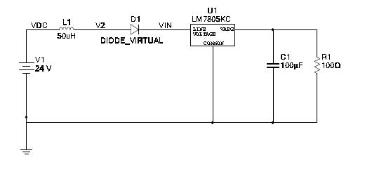
Here you have the basic squematic:


Use a capacitor between 7805 input and gnd and see if it helps,
a small electrolytic about 10uf and one 100n (mylar, mkt ) in parallel.

Alex
 
Thanks so much Alex. I've already tried this with diferent capacitor values but it doesn't help.
 

Most linear regulators consist of a reference voltage, a difference amplifier and a series pass element. The amplifier gain is quite high and as such needs good supply decoupling. You absolutely MUST add a capacitor between the input pin and ground as Alex says. The input capacitor is far more important than the output one. Treat it as though it was a decoupler across an op-amp as this is essentially what it is inside the regulator so keep its wires as short as possible and wire it directly between the pins of the regulator. Using two in parallel is a good idea, one electrolytic to act as a local reservoir and one ceramic to give low impedance at higher frequencies. Adding a series inductor makes the problem far worse, it increases the impedance at the regulator input when you should be making it as small as possible.

Brian.
 
Just as a secondary note.

Some 7805's will oscillate at 50MHz, depending on the equipment you may not notice this.

It takes very little to set them off if you do not decouple them well and watch out if you have an kind of "protection" circuit around them such as resistors or diodes that are connected directly or indirectly from the output back to the input. I've seen this happen when people have chosen to have "switchable grounds" and don't realise that the EMC tee-filter ground pin on the output side of the regulator was effectivly connected only to the ground pin of the power input EMC tee-filter to the regulator....

The first indicator the engineer had that anything was wrong was his "bench radio" went mad, the second when he noticed the lab supply he was testing with went into current limit.

Don't use 7805's or other 78xx regulators with circuits that can generate radio frequencies such as low power transmitters for amateur radio without putting low value (10-100pf) ceremics directly on the leads of the 78xx hard up against the body modern surface mount chip caps are good for this.

ALSO... it should not need saying but I've seen it done the wrong way around so many times... The smalest value cap should be closest to the component being decoupled as it reduces not just line inductance but resistance as well so the cutoff frequency and Q is that little bit higher.
 
Last edited:
You didn't tell a reasonable motivation either for the diode or for the inductor. As said, an input bypass capacitor is required for these regulators. Placing an inductor instead gives a good chance to produce oscillations, which would be a possible explanation for the observed output overvoltage. If no oscillation can be detected, the regulator must be expedected to be damaged.
 
I have to agree, good quality de-coupling caps on short leads from the input pin to the GND pin will most likely make this problem go away for new regulators, you may have damaged some of the earlier ones with VHF oscillations that may have cooked some of the internals.
Also if you have an LC input filter and you apply a step 24VDC to it, it can ring up to 48Vpk if it is unloaded - so a 33V zener (1W) on the i/p pin to gnd makes good sense too.
Regards, Orson Cart.
 
Thanks all for your replies. Every post is being very useful for me.

Ok. I'll add the capacitor to the input, thanks for your explanations. But should this capacitor resolve the problem? What I need to get is my circuit to support this inductance value at the input. I clear up this question answering to FvM post:
Hi FvM:
The diode is a simple reverse power voltage protection. The inductance is not really part of my circuit. The first problem appeared when I was doing some conducted emissions tests. I had the circuit connected to the LISN and after some attempts the circuit started to fail (communications). At the end the circuit failed completed. The reason, it was cooked (every IC was damage). As you all will know, the LISN has an output impedance of 50ohms+50uH. So I started to investigate around this inductance value. I decied to include this in my circuit looking for the same effect and I found it. So now, how can my circuit accept this inductance to the input? I've tried with a de-coupling capacitor (47uF) but the problem continues.
Orson, thanks for your advice. In the complete circuit I've a varistor of 33V from V+ to gnd before the diode as main protection.
Lurchman, very interesting comments. I didn't know about this behaviour of the 7805. I'll take into account, although I suspect that my current problem is not related with this issue.
Brian, thanks for explanations about what important are the capacitors for the regulator.

Regards.
 
If the inductor is intended as RF filter, it should be supplemented by a capacitor, otherwise it brings up stability issues and won't be very effective.
 

Thanks all. Problem resolved. Just adding a capacitor in the 7805 intput has resolved the problem. It was because the inductor oscillated with the electrolitic capacitor that I had in the 5V side of the regulator. As these oscillations were through the regulator it failed until being cooked.
Alex, sorry for my first reply, cause I told you that I had already tried to add a capacitor without successful. Maybe when I tried it the regulator was already cooked.
Now I can continue testing the conducted emissions with the LISN. If someone is interested, I've found that some manufactures fo DC/DC modules has experiment with the same problem. You can check it here:
https://archive.ericsson.net/servic...DocNo=28701-EN/LZT14601&Lang=EN&HighestFree=Y

In fact, they finally used another LISN with inductors of only 5uH, not 50uH, to avoid these problems. Even they comment that its power modules show less conducted emissions performance when the tests are done with the 50uH LISN.

Regards.
 

Status
Not open for further replies.

Part and Inventory Search

Welcome to EDABoard.com

Sponsor

Back
Top