Continue to Site

Welcome to EDAboard.com

Welcome to our site! EDAboard.com is an international Electronics Discussion Forum focused on EDA software, circuits, schematics, books, theory, papers, asic, pld, 8051, DSP, Network, RF, Analog Design, PCB, Service Manuals... and a whole lot more! To participate you need to register. Registration is free. Click here to register now.

TL431 feedback with current source for high V(out)?

Status
Not open for further replies.

eem2am

Banned
Joined
Jun 22, 2008
Messages
1,179
Helped
37
Reputation
74
Reaction score
24
Trophy points
1,318
Activity points
0
Hello,

I am doing an offline flyback with vout = 36V at 22W.
(the PWM controller is to be NCP1217)

This is how i initially intended to do the feedback circuit...........

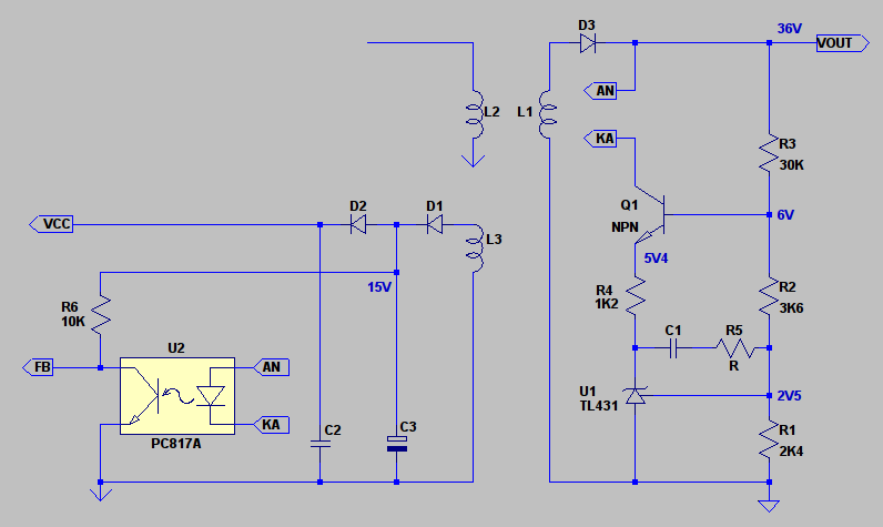
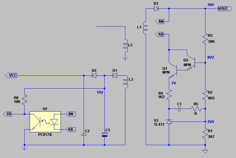
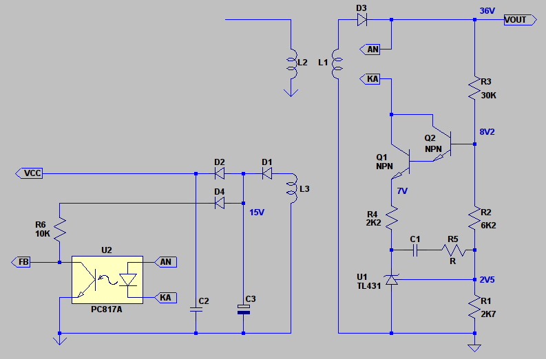
TL431 FEEDBACK CIRCUIT with bias resistor
https://i56.tinypic.com/2znpahh.jpg


...The TL431 is only rated up to 36V, so i need the 20V zener as in the above diagram.

As you know, the TL431 requires bias current of 1mA. (hence the R(bias) )
.....this bias current must of course be supplied in times of both heavy and light load....

....this is where the light-load-efficiency conundrum starts because ........

If the bias resistor, R(bias), can pass 1mA during times of heavy load, then during times of light load , it will unfortunately end up passing more current..............in fact, in times of light load R(bias) will pass almost four times as much current, due to the greater voltage across it in light load.

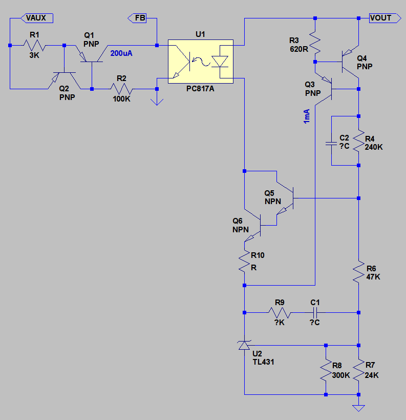
This is not acceptable , so i thought of getting rid of the bias resistor and inserting a cheap current source as follows:-

TL431 with current source (PSSI2021):-
https://i52.tinypic.com/2m6st8z.jpg

Do you believe that this circuit is OK?

Am i correct in presuming that the PSSI2021 current source will always provide 1mA or less into the cathode pin of TL431, during light and heavy load times?


PSSI2021 CURRENT SOURCE DATASHEET:
**broken link removed**

TL431 DATASHEET:
https://www.fairchildsemi.com/ds/TL/TL431A.pdf
 

The TL431 and its use in feedback with opto-isolators is always a source of consternation.

First problem is that opto-isolators have a wide tolerance in current transfer ratio.. perhaps 2:1 for any particular 'band' of device. Then their characteristics and, possibly importantly, bandwidth change with the amount of current you put through them. Then you have to add in the TL431s need for a minimum current to be in regulation.

This might be OTT but I would tend to try and ensure a nominal output current in the optos output transistor and then proceed from there,


This might still cause start up problems but I have assumed that in operation your primary side auxilliary supply is at 15V. It is connected to the collector of the opto-transistor through R6/10K. With the internal reference at about 5V then to come into regulation the opto-transistor will have to draw 1mA.

This sets up the standing current in the device as a pre-bias. In order to shut down it will have to draw 1.5mA + 185u/240uA so call that about 1.7mA. The control range is 1mA-1.7mA. If the CTR of the opto-isolator is less than 100% then, in regulation, this will guarantee at least the 1mA standing current in the TL431.

On the secondary side I have set the feedback resistor/s, R1/R2/R3 to have a standing current of 1mA, nothing to do with that in the TL431 it's just the way it happened using standard values. R2 is use to set a bias point for pass transistor Q1 at about 5.4V. It's base current will interfere but hopefully not too much...

Grrrrrr thinking about it that may well upset the overall feedback since it represents a DC path around the amplifier. Effectively is will be a resistor of Beta.R4 which is going to upset both DC precision. So I'll cunningly turn it into a darlington..


So now we get a minimum standing current in the opto, diode and transistor, with the same in the TL431 and, with a CTR less than 100%, the TL431 is guaranteed its 1mA. Plus the opto-transistor is biased up to a useful standing current to ensure its performance.

Then you adjust R4 to set the operating levels. This will not be strictly correct because CTR is generally specified with a diode current of 10mA. Assume the same figures apply at 1mA.

If your opto had a CTR range of 40%-80% and the fitted device was an 80% one then if you chose to set the TL431 Cathode at 5V you would need something like an 1K6 resistor for 1.25mA in the opto-diode and 1mA in the opto-transistor. That would put VFB at the required 5V.

To shut down you would need 1.7mA in the opto-transistor or 2.13mA in the opto-diode which would place the TL431 Cathode at about 3.6 volts so it would still be operational.

Now say the fitted device was a 40% one. Again setting the cathode at 5V you would need something like an 820R resistor for 2.43mA in the opto-diode and 1mA in the opto-transistor. To shut down you would need 1.7mA in the opto-transistor and 4.25mA in the opto-diode placing the TL431 Cathode at about 3.5V. Again still operational.

Probably too many words here however overall the adjustment maintains the loop gain. Half the CTR halves the resistor, R4, doubling the current sensitivity so they cancel and the gain remains the same. You do not need to know the CTR. You just measure the voltage on FB and pick a resistor that sets it to 5V. Everything else sorts itself out....

The way it is configured also naturally limits the control range which should aid recovery.

Last problem is that I am loading the FB pin at start up with my 10K resistor so...


I'll put in D4 to block that.

Of course I might just be trying too hard and none of the above is really necessary. I just like to have reasonably well defined operating points within a circuit and unfortunately with a TL431 and opto-isolator you have to work hard at things and add a bucket of extra bits.

One last concern would be whether things become operational during start up in order to bring the output 'up' into regulation rather than have it overshoot and then have to bring it, or let it come, back down again.

Genome
 
  • Like
Reactions: eem2am

    eem2am

    Points: 2
    Helpful Answer Positive Rating
Thankyou Genome,

I see that you have a great system going there

i note your good idea to get a 1mA standing current going and then proceeding with that.

I am not sure about the time when your above mentions 4.25mA in the opto diode, because with vout=36V, that 4.25mA will cause more than 153mW of wasted power, which is not good for the <500mW standby regulations which come in place for us here in 2014.

Also, i appreciate the 10K resistor hanging off the 15V rail.......though as with any SMPS where the bias winding is unregualted, that 15V rail will likely drop to around 10V (or even less) when in light load...which further complicates matters there.

to stop output voltage overshoot , an RC series network could be placed across the upper output divider resistor, or elsewhere, to couple the vout into the feedback loop so as to avoid overshoot.....as i'm sure you will be aware.
 
Understood. I keep forgetting about this 500mW standby and I see the point about the auxiliary supply not being regulated. As is usually the case with these things one thing or another comes along to upset the overall picture

It looks like your 1mA current source is the way to go but you might still consider using the feedback network and pass transistor to limit the cathode voltage of the TL431 with components scaled accordingly. Zener diodes are not the 'sharpest' thing on the planet..

Scratches head.

What about...


Perhaps I worry too much about the performance of opto-isolators and how they are subject to variance and the effect of that on loop gain. I still like standing currents in them and not much deviance from that current.

I've placed your current source, or its bias, in the feedback chain. Dirty maybe but then the pass transistor for the TL431 is also being driven from it. I've added a similar current source on the primary side to bias the opto-transistor.

Without checking too hard I've dropped all the operating currents. Compensation components are not defined and you still have to pick a value for R10...
 
  • Like
Reactions: eem2am

    eem2am

    Points: 2
    Helpful Answer Positive Rating
Status
Not open for further replies.

Similar threads

Part and Inventory Search

Welcome to EDABoard.com

Sponsor

Back
Top