Continue to Site

Welcome to EDAboard.com

Welcome to our site! EDAboard.com is an international Electronics Discussion Forum focused on EDA software, circuits, schematics, books, theory, papers, asic, pld, 8051, DSP, Network, RF, Analog Design, PCB, Service Manuals... and a whole lot more! To participate you need to register. Registration is free. Click here to register now.

How to connect bluetooth module and PIC ?

Status
Not open for further replies.

W_Heisenberg

Full Member level 4
Joined
Feb 27, 2011
Messages
217
Helped
6
Reputation
12
Reaction score
6
Trophy points
1,298
Location
Boston
Activity points
2,575
After looking for the proper bluetooth module for days, I have found that microchip company offers some bluetooth embedded PIC. These PICs are good yet they are so expensive(at least 100 dollar each). Can anybody gives some suggestions about buying a seperate bluetooth module ? Moreover, how do we really connect the bluetooth module and PIC ? It seems we could connect them under the rule of UART module, yet I am not sure how we do that, and what to do for initializing the UART module on PIC.

If anyone knows this, please help! If anyone had the experience building such a circuit, please tell me some thing about the circuit diagram.

Many thanks!

Sincerly
 

in a recent project we used a bluegiga wt12 module which connects to a UART
**broken link removed**

you control it using AT commands

it is easy to attach it to a development kit such as the microchip microstick
**broken link removed**

if has a header to enable you to connect to a breadboard for your own circuits

also have a look at
**broken link removed**
 
Thanks a lot
so "WT12 Class 2 Bluetooth Module" can be connected to UART of a PIC (i.e. PIC16F877) ?

i checked "WT12 Class 2 Bluetooth Module" datasheet, but couldnot find the connection diagram. Could you tell me something about the schematic diagram?

Thank you in advance.
 

for simplicity (and the PIC24 has 4 UARTs) we used serial communications
1. the BT12 serial Tx pin 26 to the Rx of a PIC24 UART
2. the BT12 Rx pin 6 to the Tx pin of the PIC24 UART
 

Attachments

  • WT12.jpg
    WT12.jpg
    23 KB · Views: 155
Thank you very much!
I found there are so many types of PIC24 offered in digikey. I guess you mean PIC24F04K, is this right?

Moreover, my whole project is applying bluetooth module to drive a LED.

So, i am thinking that I should have at least two circuits like the schematic diagram you posted above. One should be built with a button (input), as a transmiiter or remote control thing; the other should be built with a LED (output), as a receiver.
In other words, I need two PICs, two WT12 module, one switch, and one LED, is this correct?

The data would be transmitted through air between two WT12 modules, and PIC will analyze the data and drive up the LED. This is what I think, yet not sure whether this is reasonable.

Hopefully my explaination is easy to understand, and if you have any suggestions, please let me know.
Very looking forward to your reply!

Thank you very much for your help!
 

this project used a PIC24FJ256GB106 - we needed 4 UARTs as we had the Bluetooth, a GPS modem, A GSM modem and at connection to a PC serial port as well.
However, any device with a UART or USART could drive the device OK.
Initially I would make one device and pair it with Buletooth enabled laptop or similar device so can check the switch transmits OK. When that is working build the receiver with LCD
 

Thanks for answering.
If we want to check the bluetooth connection, e.g. by using a laptop, how to make the bluetooth module searching the PC bluetooth, or it is automatic?

Besides, why do we use 4 UARTs, i dont understand the GPS and GSM modem. These two modems are enabled during the project? Isnt GSM something related to 2G, which is under the control of network company?

Could you explain more? Thank you in advance.
 

You get GSM and GPS interfaced in the same module if you are very specific in using it... You can seearch for SIMCOM modems with both features... and use relay to switch over the functionality in UART if you have multiple devices on a single UART......
 

i want to use a bluetooth module to be connected with UART. Do I still need to configure GSM or GPS these things for bluetooth module?

Thanks in advance.
 

no, the GSM and GPS modules were for a specific project, we needed to know where we were and send send text messages to a server - you only need Bluetooth
It it some time since I used the BT12 but I seem to remember you tell one end to search for seach for Bluetooth devices in the area then you attempt to establish a connection. The receiver has to then acept it. You need to look at the manuals to get the appropriate commands.
 

Use Bluetooth module withcontroller and use a BT dongle and bluesoleil software to work as a server.....

You can set a default passcode and enter the same passcode in the PC to establish the connection.....
Instead of a server, you can see the data received by PC on hyperterminal , and capture the logs of the same.............
 

Who can show a schematic that uses PIC24FJ256GB106-I/PT with 4 UART ports.
Thanks you.
 

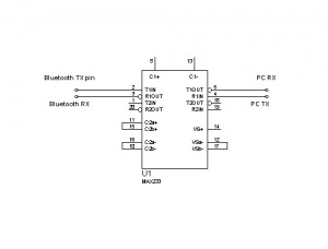
I also have the doubt for the connections of Bluetooth module and PIC.. But i have some idea about the connections.. UART interface has one of the approach for the connection of the Bluetooth device to the controller..... Because it have capability to manage all set of connections...
64_1326890283.jpg
 
Uh, I finally already made the project work. That was on last year...

Thanks for supporting.
 

Uh, I finally already made the project work. That was on last year...

Thanks for supporting.


Can you send me your project? im making a Explorer Car using Pic16f877 and bluetooth modules for controlling it, and i need the most help i can use please. Thanks
 

Status
Not open for further replies.

Part and Inventory Search

Welcome to EDABoard.com

Sponsor

Back
Top