poorren
Junior Member level 3
Hello guys,
I'm trying to design a local oscillator using a Z-comm VCO+National's PLL. In the first pass design, due to some calculation mistake, I designed a loop filter which actually lead to a phase margin 85 degree.
There's a ringing on the tuning line of VCO like this.
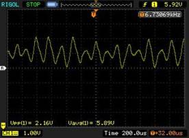
Now, I corrected the loop filter, and design a phase margin of 45 degree. The loop works fine, and the ringing disappeared. I'm very curious why the phase margin of 85 degree could lead to un-stable of loop. Furthermore, why a phase margin of 45 degree will have stable design. I don't analysis the close loop function poles, but I used a classic active loop filter, which is supposed to satisfy the Routh rule.
I am very confused on this. I'd like to hear your ideas. Thanks.
I'm trying to design a local oscillator using a Z-comm VCO+National's PLL. In the first pass design, due to some calculation mistake, I designed a loop filter which actually lead to a phase margin 85 degree.
There's a ringing on the tuning line of VCO like this.
Now, I corrected the loop filter, and design a phase margin of 45 degree. The loop works fine, and the ringing disappeared. I'm very curious why the phase margin of 85 degree could lead to un-stable of loop. Furthermore, why a phase margin of 45 degree will have stable design. I don't analysis the close loop function poles, but I used a classic active loop filter, which is supposed to satisfy the Routh rule.
I am very confused on this. I'd like to hear your ideas. Thanks.
Last edited: