Continue to Site

Welcome to EDAboard.com

Welcome to our site! EDAboard.com is an international Electronics Discussion Forum focused on EDA software, circuits, schematics, books, theory, papers, asic, pld, 8051, DSP, Network, RF, Analog Design, PCB, Service Manuals... and a whole lot more! To participate you need to register. Registration is free. Click here to register now.

Tuning Push-Pull inverter for Best Efficiency

Status
Not open for further replies.

AleXYZ

Junior Member level 3
Joined
May 12, 2010
Messages
29
Helped
4
Reputation
8
Reaction score
4
Trophy points
1,283
Location
USA
Activity points
1,697
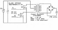
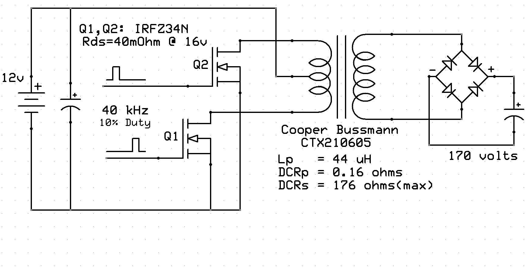
The following circuit is on a breadboard on my bench, it runs at 40 kHz with approximately 10-15% duty cycle. The end goal is to get 170-200 volts in the output as efficiently as possible.


My Question: How do I tune this Push-Pull circuit to get maximum efficiency? As it is now, most of the energy going into the circuit is dissipating out the MOSFETs as heat. (No, I haven't smoked one yet but I did slightly burn a finger.) At a guess I'd say I'm getting 5% efficiency. I am hoping for closer to 90%.

I think all of the relevant component info is in the diagram but if any other details are necessary I'll be happy to provide them.

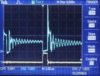
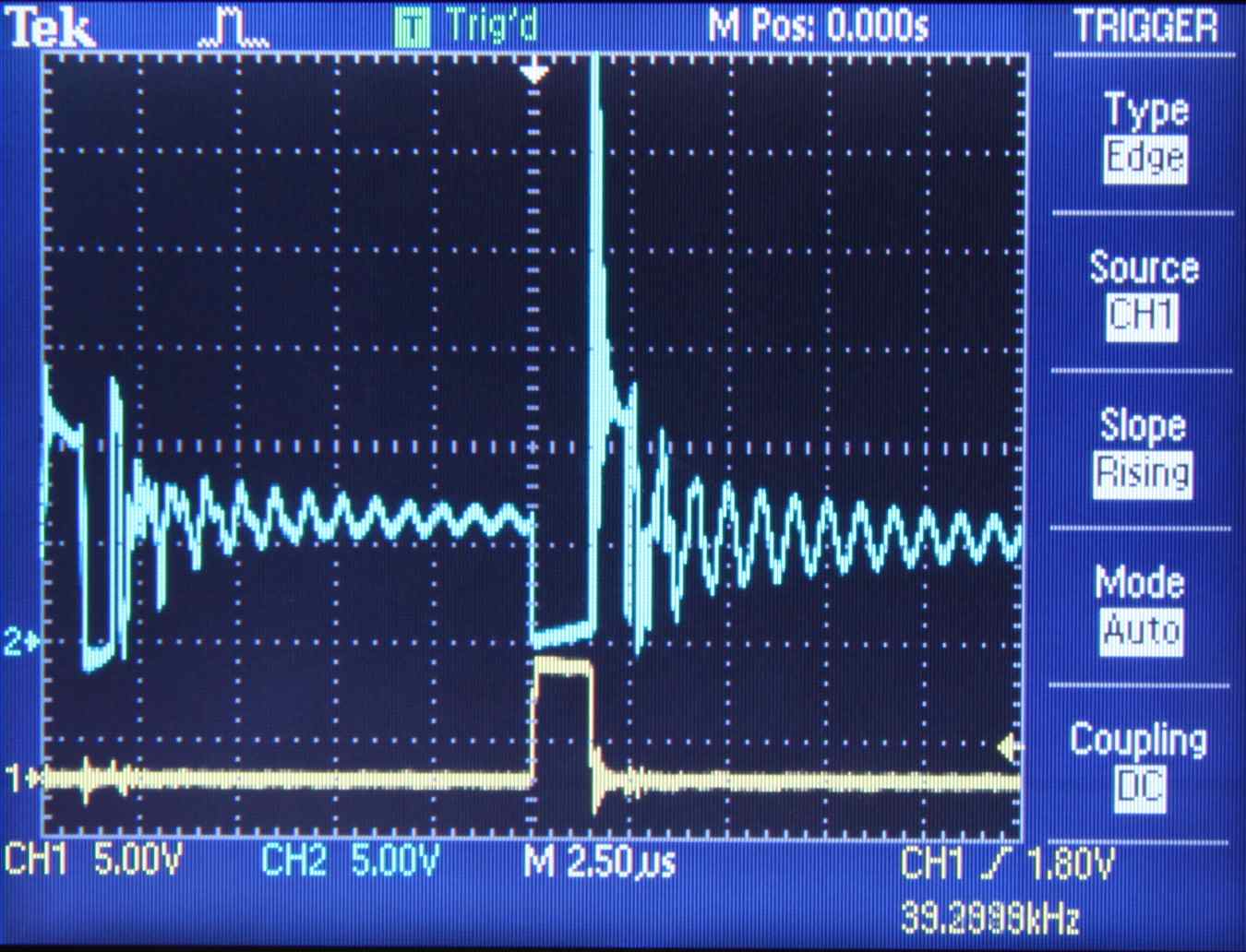
And if it helps, here is a scope image of the gate (yellow) and source (blue) for one MOSFET of the push-pull.


I scoured EdaBoard and Google for posts that might have maths or tuning for this type of circuit but came up empty. Any advice?

---------- Post added at 17:57 ---------- Previous post was at 17:15 ----------

Side Note: I am looking into Royer oscillator configuration as well, however the following document indicates that the direct drive (via PWM) method I am using can be used to achieve higher efficiency. This document, however, does not provide enough detail to do circuit tuning to achieve that efficiency.

https://www.microsemi.com/media/PDoct2004.pdf
 

Hello,

There are two things:
Normal operation (when the capacitor is charged up to the required voltage) and start-up operation (when the capacitor is empty).

Looking to your circuit:
The transformer has so called leakage inductance. This causes the voltage spike during turn-off. To reduce this spike, you need to add a snubber (can be RC circuit, tranzorb or combination of RC and D, or a capacitor only when using zero voltage crossing).

You also need some current limitation means. This can be an inductor in series with the transformer's secondary. This limits the current rate of change, enabling you to use larger pulse width (up to about 48%). A larger pulse width means that more energy per cycle is transferred to the 170V storage capacitor. You have to figure out whether your transformer can stand the v*t product. If this product is to large (for your transformer), the transformer will saturate, leading to a strong increase in current (though this increase is not seen in the secondary side).

The inductor between transformer and rectifier will also provide current limitation during start-up (when the capacitor is empty). To save components, simulation can be very helpful.

With very careful design, you can create a so-called zero-voltage switching converter. This requires tweaking of the current limiting inductor and adding capacitance across drain source. Such circuit provide > 90% efficiency.

Regarding Royer oscillator. This is a simple and good means to generate high voltage with about 90% efficiency. It works perfectly with BJT. The primary side of the transformer is used as a resonant circuit with the parallel capacitor. So the output waveform is sinusoidal and the collector waveforms are rectangular.

A capacitor in series with the rectifier can be used as limiting means. Note that maximum CE voltage is somewhat more the 3 times supply voltage, so check Vcemax.
 

You are operating the CCFL transformer far from it's intended operation conditions. These transformers have an intentionally high leakage inductance to act as a discharge lamp ballast. To determine, if efficient operation is possible at all, one must know the intended output current.
 

Looking to your circuit:
The transformer has so called leakage inductance. This causes the voltage spike during turn-off. To reduce this spike, you need to add a snubber (can be RC circuit, tranzorb or combination of RC and D, or a capacitor only when using zero voltage crossing).

Where is the R-C connected? Between MOSFET Source and ground? Should I assume the R-C constant is the same as the driver frequency? Or is it some ratio?

With very careful design, you can create a so-called zero-voltage switching converter. This requires tweaking of the current limiting inductor and adding capacitance across drain source. Such circuit provide > 90% efficiency.

This sounds ideal! I'd like to try it. Do you have a snippet of a schematic that depicts how this is configured? I am not sure the connection of "capacitance across drain source" ("drain-and-source" perhaps?) or what the value of the capacitor should be.


Today I disassembled a Pyle PNVU400 which is a 12vDC->120vAC utility inverter rated at 250 watts. It uses a push-pull circuit nearly identical to what I am trying to accomplish, though it uses the IRF3205 (much lower Rds) and a custom transformer. Measured frequency is 24 kHz. The duty cycle is 50% per MOSFET and its current consumption with no load is extremely low: 12v@0.1A. The rectified output is 148 volts.

On a scope, the MOSFET source shows a perfect square wave at 2x the input voltage. There is no noticeable ripple. I assume the transformer is tuned for harmonic saturation? (probably not the right term, but hopefully I'm close) There are no capacitors in the primary side. Just the MOSFETs and the transformer.

---------- Post added at 19:36 ---------- Previous post was at 19:33 ----------

You are operating the CCFL transformer far from it's intended operation conditions. These transformers have an intentionally high leakage inductance to act as a discharge lamp ballast. To determine, if efficient operation is possible at all, one must know the intended output current.

What do you mean by far? Cooper-Bussmann documentation says frequency range is 40-80 kHz (I'm using 40) and input voltage is 20 volts max. I'm using 12 volts.

The transformer is rated at 6 watts max output. My application needs 1-5 watts (variable) at about 170 volts.
 

If, as FvM, says, it is a transformer with high leakage inductance (between prim and sec), it can be of use as you can use that as the current limiting means. However when this leakage inductance is between the two primary sides, it is a bad choice for your topology. Leakage inductance manifest itself like there is an inductance in series with your transformer primary windings (that is not coupled with the secondary winding).

The snubber networks are between source and drain (both mosfets), value depends on power and leakage inductance of transformer. Your assumption is not OK. Do a search on snubber networks to familiarize yourself with them. You can also use zener diodes with sufficient breakdown voltage (about35V), parallel with drain and source.

Given 20 V supply and 40..80 KHz (according the specification), rulls out the saturation issue in your 12 V application. Does the spec show this transformer in push-pull operation also?

I don't understand what you mean with "harmonic saturation".

What type of diode did you use?
 
Last edited:

The snubber networks are between source and drain (both mosfets), value depends on power and leakage inductance of transformer. Your assumption is not OK. Do a search on snubber networks to familiarize yourself with them. You can also use zener diodes with sufficient breakdown voltage (about35V), parallel with drain and source.

I understand the basic theory behind the snubber network. But the purpose of it is to dissipate power from inductive flyback when the MOSFET turns off, right? I don't see how dissipating power is going to make the circuit more efficient. As an experiment I used a series snubber of 100 ohms and 0.1 uF. This did not improve the circuit efficiency. (These values weren't exact nor were they arbitrary, but seeing as how they did not remotely affect the overall efficiency I am not convinced a snubber network will solve this problem.)

Given 20 V supply and 40..80 KHz (according the specification), rulls out the saturation issue in your 12 V application. Does the spec show this transformer in push-pull operation also?

Cooper-Bussmann does not have sample circuits in their documentation. Google searches for "CCFL inverter schematics" show that most of them are used as push-pull. The CTX210605-R I am working with has a feedback winding as well, but since my circuit is not self-resonant this winding is not connected (nor depicted) in my schematic above. Most of the circuits I find of course use Royer. One of the reasons I need to use PWM instead of Royer is to have CPU control of the output current. The output wattage demand will vary; it will not remain constant. My goal is constant output voltage and variable current, not the other way around.


I don't understand what you mean with "harmonic saturation".

Sorry, I just don't know all the terminology related to inductive circuits. What I mean to say is that the scope trace on the primaries (or source pin of the MOSFETs, same thing) is a perfect square wave. It goes from 0 volts (MOSFET-ON) to 24 volts (MOSFET-OFF) with no visible ringing. I assumed that this means the transformer was driven in a saturation mode which was obtained by the harmonic frequency, which I measured at 24 kHz. I know this is a bad assumption on my part, but if it is what exactly am I seeing?

Whatever it is, the efficiency and output of the Pyle PNVU400's inverter is almost exactly what I'm trying to achieve. If it weren't that the PNVU400 costs $45 each, I'd just buy them and cut them apart for this project. I am hoping to make this inverter in about $10-15 in parts. Less if it were possible.
 

I checked the datasheet also (the type number was in your drawing). As this transformer is rated for 2000V output (ratio = 1:67), your design will unlikely result in an efficient solution to make 170V out of 12VDC. I think you should find a transformer with less turns ratio.

When looking to the primary inductance (44uH, resulting in about j11 Ohms at 40 kHz), this transformer is ideal for a Royer type oscillator, as it has a feedback winding also.

Royer circuits can also be controlled by controlling the current through the series inductor (with buck like PWM circuit). When you have a large 170V capacitor, the proces time constant can be long, hence reducing loop instability problems. I agree, with direct control you are more flexible.

I implemented such an application (with Royer oscillator) that had to charge a capacitor. the control loop is just an hysteresis on-off type that keeps the capacitor voltage at 250Vdc, The transformer is a costum design.
 
Last edited:

What do you mean by far?
You surely noticed the nominal output voltage of 900 V and the 1:67 windings ratio.
A reverse connected standard off-mains flyback transformer would much better fit the application.
 

i m designing 500 VA sinewave inverter using pwm.
my pwm frequency is 6 khz, i m using push pull configuration in power section
i want to know whether same type of transformer (12-0-12/ 220V) is used for square wave inverter and sine wave inverter( PWM freq is 6 khz)?
if different type of transformer is required for sine wave inverter, then, what are the specifications of that transformer required?

please reply on my mail id : manishpatel_79@yahoo.com

right now i m using center tapped transformer (12-0-12/220V)
my problem is if i connect bulb of 80 watt it lights very dim.
primary current is only 2.2. amp

to drive 500 w load properly what i should do?
where can b the problem?
what should i check?

please reply


Hello,

There are two things:
Normal operation (when the capacitor is charged up to the required voltage) and start-up operation (when the capacitor is empty).

Looking to your circuit:
The transformer has so called leakage inductance. This causes the voltage spike during turn-off. To reduce this spike, you need to add a snubber (can be RC circuit, tranzorb or combination of RC and D, or a capacitor only when using zero voltage crossing).

You also need some current limitation means. This can be an inductor in series with the transformer's secondary. This limits the current rate of change, enabling you to use larger pulse width (up to about 48%). A larger pulse width means that more energy per cycle is transferred to the 170V storage capacitor. You have to figure out whether your transformer can stand the v*t product. If this product is to large (for your transformer), the transformer will saturate, leading to a strong increase in current (though this increase is not seen in the secondary side).

The inductor between transformer and rectifier will also provide current limitation during start-up (when the capacitor is empty). To save components, simulation can be very helpful.

With very careful design, you can create a so-called zero-voltage switching converter. This requires tweaking of the current limiting inductor and adding capacitance across drain source. Such circuit provide > 90% efficiency.

Regarding Royer oscillator. This is a simple and good means to generate high voltage with about 90% efficiency. It works perfectly with BJT. The primary side of the transformer is used as a resonant circuit with the parallel capacitor. So the output waveform is sinusoidal and the collector waveforms are rectangular.

A capacitor in series with the rectifier can be used as limiting means. Note that maximum CE voltage is somewhat more the 3 times supply voltage, so check Vcemax.
 

I understand the basic theory behind the snubber network. But the purpose of it is to dissipate power from inductive flyback when the MOSFET turns off, right? I don't see how dissipating power is going to make the circuit more efficient. As an experiment I used a series snubber of 100 ohms and 0.1 uF. This did not improve the circuit efficiency. (These values weren't exact nor were they arbitrary, but seeing as how they did not remotely affect the overall efficiency I am not convinced a snubber network will solve this problem.)
Certain snubbers can definitely improve efficiency. A dv/dt limiting RCD snubber can decrease turn off losses in the FETs by keeping drain voltage low while drain current is falling. If done right, the savings in the FET can be greater than the dissipation in the snubber. This generally doesn't apply to peak limiting snubbers like the classic RC or the RCD clamp snubber.

But anyways, you first need a better suited transformer, otherwise you'll never get decent results.
 

Status
Not open for further replies.

Similar threads

Part and Inventory Search

Welcome to EDABoard.com

Sponsor

Back
Top