Continue to Site

Welcome to EDAboard.com

Welcome to our site! EDAboard.com is an international Electronics Discussion Forum focused on EDA software, circuits, schematics, books, theory, papers, asic, pld, 8051, DSP, Network, RF, Analog Design, PCB, Service Manuals... and a whole lot more! To participate you need to register. Registration is free. Click here to register now.

Overvoltage protection circuit

Status
Not open for further replies.

bababui

Junior Member level 3
Joined
Apr 12, 2009
Messages
26
Helped
2
Reputation
4
Reaction score
1
Trophy points
1,283
Location
USA
Activity points
1,474
Hello,
I'm building a circuit that will protect my data collection equipment against suddent spikes in voltage and was wondering if someone can add some pointers.

I am reading in voltage signals that are typically on the order of 1-2 volts. My requirements are that the protection circuit will limit the voltage between either of the inputs and the ground, and between two signals to say 30V.

Spikes can come not only from signals being read but ground as well.
 

You do not say what sort of "data collection " interface you are using. Best thing is to use cat5/6/? screened cable with the screen earthed at both ends. Pretty bomb proof. The only problem with this is that of "earths" at each end having some different voltages on them. This usually in the order of 0->10V UNLESS you are near a medium wave transmitter where the voltage could be 100V sine wave at the transmission frequency (.5-> 1.5 Mhz)
Frank
 

Here are some high-level concepts to get you thinking about mitigation options.

1) Shield the sense wires, so external signals don't create large transients on your (I'm assuming high-impedance) sense wires... see chuckey's comment on CAT5, good place to start.

2) Add some additional impedance to the line (if you are sensing a voltage on a low-impedance circuit, add a 1K, or similar, resistor in series with a high-impedance sensing circuit (A/D, etc)

3) Add some type of voltage clamp to the sense lines to prevent them from going above a set threshold.
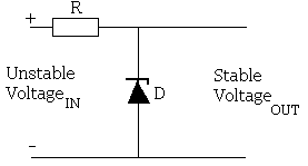
For this, I'd suggest zener diodes. Hang a zener on each line, in shunt to ground. You should also add a moderate-sized series resistor (10-1000 ohms) to your sense line, so the zener has something to work against.
zener-diode-voltage-regulator.gif
 

Thank you for your suggestions gents. That is pretty much what I have been doing. What if I want to protect against spikes at the ground end as well?
 

Thank you for your suggestions gents. That is pretty much what I have been doing. What if I want to protect against spikes at the ground end as well?

Ground-bounce is not a fun problem to solve. The best approach would be to bond the ground planes of the system under measure and the measurement circuit together very well... e.g. thick wire between ground metals, so they are at an equivalent voltage, even with large transient currents (poor bonding + high current = lot of voltage induced in ground path).

Can you draw us a better picture (mentally or physically) of the system connections, and tell us what kind of system this is built into?
 

So one problem I'm still working on is the groundbonce. If I'm expecting that there is a possibility my ground will see some sudden voltage spikes for whatever reason, then I was thinking to have two grounds right next to each other (metal stakes into the ground) and have a circuit that essentially subtracts onen from the other and the output of that circuit will be visible to the rest of the circuit as ground. So if the ground rods see some voltage spike, they will subtract from meach other and the circuit will see zero basically.

Somethinig like this:
**broken link removed**

but the problem is this circuit itself also has a ground. so I guess I can have a 3rd ground right next to the other two.... iduno.

plus, is there an opamp that can take a really high surge and is relatively cheap.

plus, even if this works, am I overlooking something?


Please comment on this idea and any suggestions.
thanks

You could use the difference amplifer to convert each sensed voltage into a "common grounded" signal within the monitoring circuit. Using the figure on your linked site, connect V1 to the measured voltage, and connect V2 to the sensed-system's ground. This will give you a voltage rise on the monitored system, which the diff-amp will convert to a voltage relative to the monitoring circuit's own ground. Set up the resistors for unity gain, so you get 1V in = 1V out.

Op-amps that handle high-surges are an unlikely find, high-speed and high-voltage protection are design features that are in opposition to one another. I'd stick with designing the circuit well in order to handle these transient events.
 

Thanks for all your tips. One more question. Instead of making my own circuit, there's got to be over the shelf gadgets that I can use for this purpose. Something that has a replaceable fuse that would blow if voltage spikes to high. I'm using NI9239daq for data aquisition, so I'm trying to protect that.
 

Thanks for all your tips. One more question. Instead of making my own circuit, there's got to be over the shelf gadgets that I can use for this purpose. Something that has a replaceable fuse that would blow if voltage spikes to high. I'm using NI9239daq for data aquisition, so I'm trying to protect that.

Not that I'm aware of. It'd be really cheap and simple to "roll your own" on a piece of any-board (perforated circuit board for prototyping), using a dual-opamp (14 pin DIP), two leaded 3.3V zener diodes and a sprinkling of leaded resistors. Check out Digikey, Newark, etc for parts, if you don't have local access to standard electronic components.

The tricky thing about this electronics business, you have to do a lot of the custom stuff yourself.
 

Ok, So I have a circuit that basically consists of zener diodes and resistors and if the input signal is very high then zeners will conduct current and my data aquisition equipment won't see high voltage. But what if my equipment runs on batteries and I don't have earth ground. What am I connecting the other size of the zener to? Negative terminal of the battery? Would a high input voltage spike cause a problem there?
 

Ok, So I have a circuit that basically consists of zener diodes and resistors and if the input signal is very high then zeners will conduct current and my data aquisition equipment won't see high voltage. But what if my equipment runs on batteries and I don't have earth ground. What am I connecting the other size of the zener to? Negative terminal of the battery? Would a high input voltage spike cause a problem there?

Correct: you want to tie the zener to the ground of the sensor circuit you are trying to protect. What you are trying to do is keep high voltages off of the sensitive circuits inside the DAC. By putting the zener in shunt to the circuit ground, the current surge (that would create the high voltage) is directed to ground through the diode, instead of encountering the high-impedance of the DAC and generating a large voltage potential (small I * big R = moderate/big V).

Even in a battery-operated system, you still have some finite resistance between the sensor circuit ground and the sensed-circuit ground (unless you are in an absolute vacuum, suspended in freepsace). There will ALWAYS be a ground return path in the real-world, even if it's a super-high reistance (plastic circuit case, wodden table, dirt... for example).


i guess what I'm trying to understand is what would happen if there was a very high spike at the input and zener would allow this high current to flow to the battery negative terminal. If the spike is sufficiently high, can that have negative effects on the battery or anything else.
 

Status
Not open for further replies.

Similar threads

Part and Inventory Search

Welcome to EDABoard.com

Sponsor

Back
Top