Continue to Site

Welcome to EDAboard.com

Welcome to our site! EDAboard.com is an international Electronics Discussion Forum focused on EDA software, circuits, schematics, books, theory, papers, asic, pld, 8051, DSP, Network, RF, Analog Design, PCB, Service Manuals... and a whole lot more! To participate you need to register. Registration is free. Click here to register now.

Theory on flyback diode needed in motor interfacing

Status
Not open for further replies.

sysysy

Member level 3
Joined
Nov 11, 2010
Messages
56
Helped
2
Reputation
4
Reaction score
1
Trophy points
1,288
Activity points
1,801
Hi,

I have few question wish to ask.
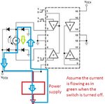
In my project, i understand the interfacing between my motor and l298 motor driver need 4 of the flyback diode.

From some information, the diode is for absorb the pulse energy when suddenly turn off the motor due to the inductor effect. In other word, mean the diode is to protect the driver or any nearest equipment.

My question is why the diode is connect in the way as below schematic example:
https://t1.gstatic.com/images?q=tbn:ANd9GcTS8QbeaDdV2C-B4v3KdtWDOC1MlImmJKOXR4WpnzK1xMLFk4HNMA

Anyone can explain how the diode can absorb energy in this schematic? why reversed bias in Vdd and forward bias in gnd? can anyone explain little bit about this design.

Secondly, i also look some information saying that some driver dun need flyback diode but some need. is this depends on how the transistor or mosfet connnect with the motor? why?

Hoping someone can share the knowledge if any.

Thanks alot.


Regards,
sysysy.
 

The theory behind the clamping diode is explained by the following equation.
V = -L*di/dt. If you don't know calculus, in plain English it says "the voltage across an inductor is equal to the inductance (in Henrys) multiplied by the time-rate-of-change of the current through it." To show how big the votlages can get, here is a quick example. Let's assume the motor winding has an inductance of 10 mH (I'm pulling these numbers out of thin air), you are drawing a constant 0.4 Amps, and turn off the current in 100 microseconds. The result would be V = -0.010 * 0.4/0.0001 = -40 V. If the FETs in your motor driver chip are only rated to 35V of reverse-bias, then you have released the magic smoke and killed the driver.

So, to keep this turn-off transient voltage (generated by back-EMF, EMF = electromotive force, more commonly called voltage) from frying your driver, you need to clamp it to a fixed voltage level. The two readily available voltages are +Vcc2 and Ground. Since the motor in your schematic is shown to be bidirectional, the current can flow "up" or "down", through it.

Assume that we are applying a positive voltage to the top terminal of the motor, and the bottom terminal is being pulled to ground by the driver. The current will flow from top to bottom. When the motor driver turns off, the energy stored in the magnetic field of the motor windings (inductors) creates a voltage with a polarity in reverse to the direction of current flow. In this case, you will create a voltage potential from the top terminal, to the bottom terminal (visualize this by removing the motor and dropping a 40V battery in it's place). Since the top terminal is one diode-drop (0.2V or 0.7V) above ground, it will want to remain there when the top-right diode is conducting. So, the bottom of the voltage potential is at ~0.2V. The other side of the motor's induced voltage potential will be at 40.2V. If you look at the bottom terminal, 40 volts there will cause the diode on the opposite side (bottom-left) to turn on, allowing charge from the voltage potential (motor back-EMF) to flow into the +Vcc2 supply.

The same thing happens if the motor is driven in the opposite direction, except the polarity of the transient voltage will be reversed, and the oposite diodes (top-left and bottom-right) will conduct to remove the excess charge that is stored in the motor's windings at turn-off.
 
Hi,

enjunearm really thx alot for ur explanation.
Anyway, juz my understanding is not really gud.

1 things wanna ask, is it in different direction of motor turn. then only certain diode will be conducted?
Sorry for asking more,

may i know let say now the motor is running forward, then suddenly turn off or switch...
how the diode take effect? let the excessive voltage flow to vdd or gnd? how they absorb energy?
what is the path that the energy will go through?

thanks.
 

Hi,

enjunearm really thx alot for ur explanation.
Anyway, juz my understanding is not really gud.

1 things wanna ask, is it in different direction of motor turn. then only certain diode will be conducted? Sorry for asking more,

may i know let say now the motor is running forward, then suddenly turn off or switch...
how the diode take effect? let the excessive voltage flow to vdd or gnd? how they absorb energy? what is the path that the energy will go through?

thanks.

The diodes only conduct when a voltage larger than +Vcc2 is present, otherwise they aren't forward-biased and will not turn on (0.2V and 0.7V, for Schottky and silicon didoes, repsectively).

The diodes don't primarily absorb energy... they will burn a little off as heat, due to the semiconductor material. These diodes simply provides a one-way path for charge to flow. When the motor is turned off, a lot of charge is held in the motor windings that has to get out (to reach equilibrium). The paths through the driver are turned off, so the only path "out" is through the diodes. The diodes only conduct for a brief moment of time, when the motor is turned off and the transient voltage is high enough to bias the diodes on. Once the excess charge in the motor windings bleeds off, the voltage falls and the diodes no longer conduct.
 

Okok...thanks 1 more time...

that mean when there is a over voltage, then the diode juz take effect, and the diode is provide the path to let excessive charge flow out.
so the charge is either flow to vdd or gnd? i will ask this question is becoz i c the cathode of the diode is face the vdd... and another is anode face gnd.

laz time when i constructed circuit, i make 2 cathode of diode face vdd and another 2 cathode of diode face to gnd, and my motor is never running.
But after i notice my mistaken and change it and the motor did run.... but i always dunno how this circuit get work. besides only juz blindly follow the schematic and make things run, i found that i lean ntg.... now start understanding theory why this all circuit really can do all task and how.

hope u dun mind to my poor understanding level.
 

The attached diagram may help you.

Assume that the current is flowing through the motor in the direction of the green arrow.

When the IC switches off, the inductance, in accordance with Lenz's Law, will keep the current flowing in the same direction, ie. as in blue.

The energy stored in the inductance of the motor will therefore be dissipated as :-
heat in the windings, heat in the diodes, heat in the power supply and some will radiate in space as an electromagnetic wave.
 

Attachments

  • Motor.jpg
    Motor.jpg
    67 KB · Views: 146
very great explanation enjunear, thanks alot.

I have a question, how should I decide on the voltage and current rating for the flyback diode?

I would assume the voltage has to do with V = -L di/dt of the inductor, and this voltage is probably different than the voltage of the power source...am I missing something?
If you look at the diagram I posted you will see that the max voltage across the diodes is approx equal to that of the power supply.

It has nothing to do with V = -L di/dt.

The power rating of the diode is determined by the current that will pass throught it, the voltage across it at that current, the duration of the current pulse and the duty cycle.
 

Status
Not open for further replies.

Part and Inventory Search

Welcome to EDABoard.com

Sponsor

Back
Top