Continue to Site

Welcome to EDAboard.com

Welcome to our site! EDAboard.com is an international Electronics Discussion Forum focused on EDA software, circuits, schematics, books, theory, papers, asic, pld, 8051, DSP, Network, RF, Analog Design, PCB, Service Manuals... and a whole lot more! To participate you need to register. Registration is free. Click here to register now.

[SOLVED] Pspice simulation of MFB chebyshev filter

Status
Not open for further replies.

oshaye3

Member level 3
Joined
Aug 4, 2010
Messages
62
Helped
0
Reputation
0
Reaction score
0
Trophy points
1,286
Location
london
Activity points
1,822
Hi all,

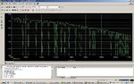
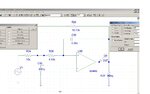
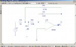
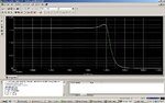
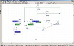
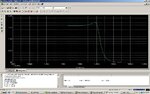
I used matlab to calculate the components values to design chebyshev filter It is a second order low pass filter. The simulation does not give me exact response and ripples everywhere. I pasted below the code and results below. I attached the simulation and the schematics as well. Is it the way I assigned value to the R1 that caused this abnormal response.

Please any response from this forum


code:
fc = input('\n Enter the Cutt off frequency for your filter:');
C_A = 1 ;
C_B = 0.872 ;
C_C = 0.636 ;
R1 = 10 % kohms
R4 = R1/C_C % kohms
R3 = R1*R4/(R1+R4) % kohms
C5 = 1000*C_B/(2*R1*2*pi*fc) % uF
C2 = 1000*C_A/(R1*R3*C5*2*pi*fc) % uF


Results:

Transfer function:
1
---------------------
s^2 + 2.373 s + 3.314


Enter the Cutt off frequency for your filter:1500

R1 =

10


R4 =

15.7233


R3 =

6.1125


C5 =

0.0046


C2 =

0.3752
 

Attachments

  • simu.jpg
    simu.jpg
    233.6 KB · Views: 171
  • sche.jpg
    sche.jpg
    100.4 KB · Views: 185

check your simulation step.

hock
 

1. You mixed up OP inputs.
2. It's not clear what kind of OP you're using. Is it an ideal OP?
3. 10 nF is somewhat different from 4.6 nF, isn't it?

P.S.:
4. I would expect the smaller capacitance value for C20. Are you sure about the assignment?
 
Last edited:

Yes, I chose a value for r24 but not c20. I used the MFB. any suggestion how to manipulate the equation to design chebyshev response. I have changed the values, I could see the error. My Pspice is giving this error ! " Unable to start application pspicead.exe
 

I was under assumption, the values had been calculated for the choosen MFB topology.

Unable to start application pspicead.exe
Hasn't to do with the simulation circuit.
 

I know that the "Unable to start application pspicead.exe " has nothing to do with the simulation, but on the libraries which I do not know how to rectify?

What do you mean under assumption, I thought you were aware that it is MFB topology. Generally, I want to ask this question. What is the best way to calculate the component values of MFB? I mean different textbook uses different method, some will define m and n to calculate the components. I believe that designing and calculating for filters should be easy, alas it is cumbersome for me at the moment . I am sorry for all these long words!
 

There are many errors.

1- In the equations
Code:
R1 = 10 % kohms
R4 = R1/C_C % kohms
R3 = R1*R4/(R1+R4) % kohms
C5 = 1000*C_B/(2*R1*2*pi*fc) % uF
C2 = 1000*C_A/(R1*R3*[B]C5[/B]*2*pi*fc) % uF
Has a bug (mine, of course), in the last equality, C5 is already transformed in frequency.

Then, fixing it, and scaling for C in nanoFarads:
Code:
C_A = 1 ;
C_B = 0.872 ;
C_C = 0.636 ;

fc = 1500 ; w = 2*pi*fc ;

R1 = 10 % kohms
R4 = R1/C_C % kohms
R3 = R1*R4/(R1+R4) % kohms
C5 = C_B/(2*R1) ; C2 = C_A/(R1*R3*C5);
C5 = 1e6/w*C5 % nF 
C2 = 1e6/w*C2 % nF


2- In the image, you have inverted de capacitors. C5 is the feedback capacitor and C2 goes to gnd.

3- There are something wrong with the simulation parameters, but i do not use pspice (i use LTspice)

------------------------------------------------------------------


Note that the design of these filters involve 3 steps:
1 - Estimation of the values of C2 and C5 of "good behavior". (what you've done)
2 - Rounding to commercial values.
3 - Recalculation of the R's values with tolerance 5%, or 1% if necessary (high-order filters).
 
What is the best way to calculate the component values of MFB? I mean different textbook uses different method
I think, the calculation methods are varying according to the design goals, e.g. fix resistors, caculate capacitors or (more reasonable in practice) choose capacitor values, calculate resistors. Of course it involves solving a quadratic equation, so it has some complexity. I don't know, why you designed a gain of 1.57 (R25/R24) for your filter?

Many people (me too) avoid the hand calculation by using an existing filter tool. But the result should be the same, hopefully.

P.S.:
There are something wrong with the simulation parameters.
Not necessarily. I think, the strange result is caused by wrong connection of the OP, as already mentioned.
 
I don't know, why you designed a gain of 1.57 (R25/R24) for your filter?
This is a "remaining parameter" of the other thread.
He put as transfer funcion 1/(s^2 + 2.373 s + 3.314) but the values obtained are for 1/(s^2 + 0.872 s + 0.636)
 
Thanks, FVR as you said the C20 has the problem on which Eduardo has corrected. The use of the OPAMP is neccessary at the moment. I will update you ASAP as when I simulate the filter
 

I have put the simulation and schematics now, which is alright. I used the transfer function with the results pasted below. I attached the schematic and simulation as well. Thanks FVR and Eduardo for your wonderful response.

Transfer function:
1
----------------------
s^2 + 0.6449 s + 0.708


Enter the Cutt off frequency for your filter:1500

R1 =

10


R4 =

15.7233


R3 =

6.1125


C5 =

4.6261


C2 =

39.8131
 

Attachments

  • sche.jpg
    sche.jpg
    103.1 KB · Views: 130
  • simu.jpg
    simu.jpg
    185.6 KB · Views: 135

The amplitude characteristic seems reasonable, strange indeed as positive and negative OP input are still mixed up. Or did you invert the OP gain?
 
:? These values are for 1/(s^2 + 0.872 s + 0.636) again

Please, put a big Don't forget label in the parameter definition
Code:
C_A = [B]1[/B] ;
C_B = [B]0.872[/B] ;
C_C =[B] 0.636[/B] ;
.................
or rewrite your data input method.
 
FVR Thanks, I have flipped it back to as Negative FB . I attached it again. Thanks.
 

Attachments

  • sche.jpg
    sche.jpg
    103.1 KB · Views: 150

FvM, could be an annoying sim issue. some simulators won't latch for backwards inputs until clipping occurs. for an example, a buffer's gain of A/(1+A) is pretty much 1 if A is large and positive or large and negative! Makes an interesting interview question to see how well people deal with contradictory information. (I know its a latch, but the math doesn't work...)
 

Thanks Eduardo, It is true! I thought I have change the parameters for C_A, C_B,C_C. It is still alright. I am trying to get just chebyshev response. The question that I want to ask is this,

What about if I do not want to set a parameter definition for C_A, C_B, C_C, but to calculate the components based on the number of transfer functions generated. Is it possible? I mean the components is calculated as based on the coefficients of the TF. Since we have polyfact, can a code be written to identify the coefficients of C_A, C_B and C_C and then use it to calculate for each stage of the transfer function. Any Idea. Thanks
 

FVR, there is a mixed up in my folders. I have attached the correct schematics. I have resolved this schematics. I have located the right schematics.

Thanks
 

Attachments

  • sche.jpg
    sche.jpg
    110.8 KB · Views: 120
  • simu.jpg
    simu.jpg
    187.8 KB · Views: 129
Last edited:

What about if I do not want to set a parameter definition for C_A, C_B, C_C, but to calculate the components based on the number of transfer functions generated. Is it possible?

Yes, you can start from de normalized polynomial (factorization by roots) from the factorized polynomial (see tables of analog filters), then a single routine who return all values, there's no need of MatLab TF function.

----------------------------------------

But... there are many details in the design of filters that make it a little hard to write if wish a non iterative process to reach satisfactory values.

One thing is to make designs in order to better understand the process. But if what you need is a standard filter, there's no sense to reinvent the wheel -> there's a lot of software for it.


For example, download **broken link removed**, and save a lot of work.

FPro uses the criterion of setting the value of feedback capacitor, then, the input impedance produced may be very low or high -> manually assign a value until the impedance is within proper limits.
 
Thanks Eduardo, I know there are softwares for it. The tutor want me to design writing my own software and then compare it with my theoretical calculations.I thought since we can write proper equation to design the second order, may be it is much easier to cascade others by the same program we have written.

Refering to my first question, I am trying to say instead of writing parameters for C_A, C_B, C_C in this equations. I wanted to write a program suppose I say( never mind the program is not perfect)
C_A=den2(1)
C_B=den2(2)
C_C=den2(end)

and I incorporate it with the program. Can it work ? I do not know how to express it further. Cheers!
 

Status
Not open for further replies.

Similar threads

Part and Inventory Search

Welcome to EDABoard.com

Sponsor

Back
Top