Continue to Site

Welcome to EDAboard.com

Welcome to our site! EDAboard.com is an international Electronics Discussion Forum focused on EDA software, circuits, schematics, books, theory, papers, asic, pld, 8051, DSP, Network, RF, Analog Design, PCB, Service Manuals... and a whole lot more! To participate you need to register. Registration is free. Click here to register now.

why this not work(pic16f627 and simple code)

Status
Not open for further replies.

wayu_ix

Newbie level 6
Joined
Dec 18, 2010
Messages
12
Helped
0
Reputation
0
Reaction score
0
Trophy points
1,281
Activity points
1,353
hi everybody i new pic programing and you can help me.
first..
this my code by mikroc

void main()
{
TRISB=0b00000000;
while(1)
{
portb=0b00111111;

}
}

i already build this code to hex file
and Write to pic16f627a by topwin6 and topwin2007 programer
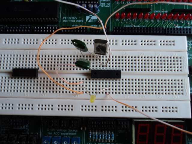
but this not work in circiut board \
pleas...zoom the way for me
 

try this code...

void main()
{
TRISB=0b00000000;
do
{
portb=0b00111111;
}
while (1)
}
 

Hi,
Goto Project > Edit Project and set the configuration bits properly. Then in TOPWinen set the configuration bits properly as well and check against the datasheet that you've got the right configuration setting.

The code appears fine, so you must have gotten the configurations settings wrong.

You might attach your mikroC project and source files if you aren't sure how to do it.

Hope this helps.
Tahmid.

---------- Post added at 22:47 ---------- Previous post was at 22:45 ----------

Can you also show us the hardware connection? Maybe you got something wrong there.


this my hardware
pic16f6271
xt 4 MHz
vdd 5 vdc
c 0.001uf
help plz...
thank you.
 

Replace the capacitors by 22pF each. 1000pF(0.001) is way too much)
Also, Never leave pin4(MCLR) open and floating. Connect it to vdd(pin14) with a 10K resistor. LED needs a series resistor !!!
 

Hi,
As suggested, connect MCLR to 5v via 10k resistor. This tells the microcontroller that it is not to be reset and it is to keep on working.
Connect a resistor between LED and PIC pin. Those capacitors are not really necessary, but if required you might replace them with 15-22pF but they aren't really necessary.
Have a capacitor smooth out the power line by placing a capacitor between the 5v and ground.
Place a 0.1uF between the PIC VCC and VSS.

Hope this helps.
Tahmid.
 

thank of all help ..
i can pass first step..
 

Status
Not open for further replies.

Part and Inventory Search

Welcome to EDABoard.com

Sponsor

Back
Top