Continue to Site

Welcome to EDAboard.com

Welcome to our site! EDAboard.com is an international Electronics Discussion Forum focused on EDA software, circuits, schematics, books, theory, papers, asic, pld, 8051, DSP, Network, RF, Analog Design, PCB, Service Manuals... and a whole lot more! To participate you need to register. Registration is free. Click here to register now.

igbt goes short circuit

Status
Not open for further replies.

adnan_merter

Full Member level 3
Joined
Jan 23, 2008
Messages
160
Helped
6
Reputation
12
Reaction score
6
Trophy points
1,298
Location
The most beautiful city of the world
Activity points
2,526
hi all,

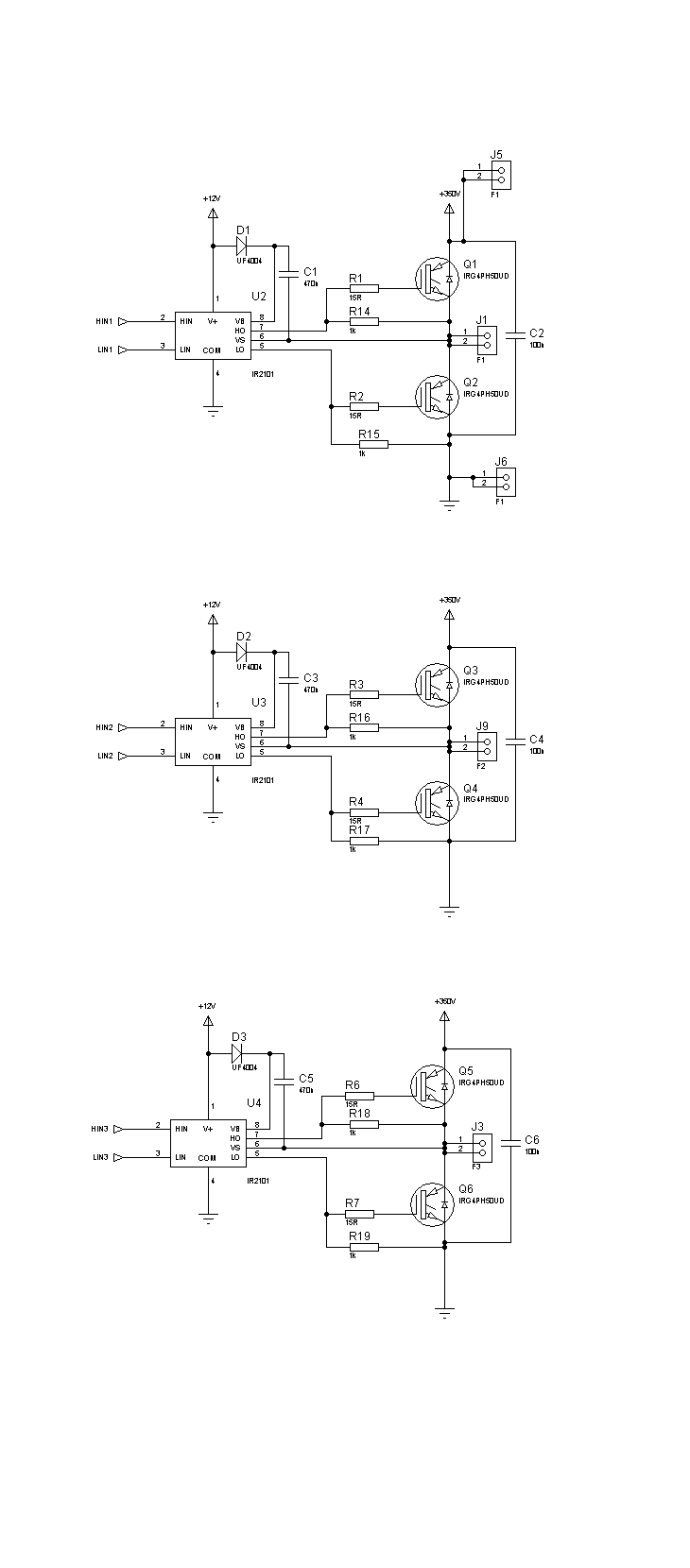
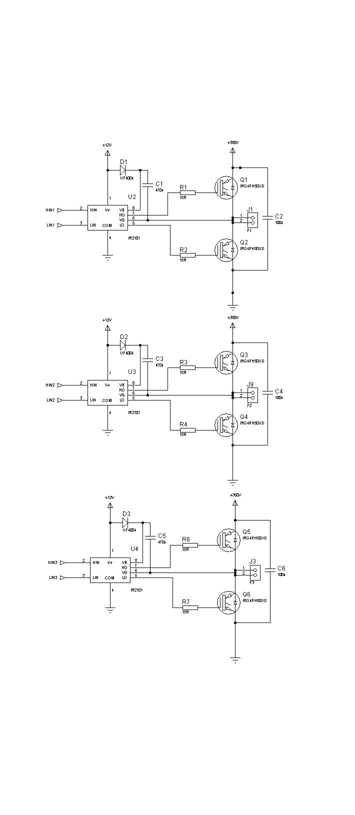
i designed a simple circuit to control a 3 phase ac motor and used igbt module for switching

but, whatever i tried, i couldn't succeed to apply them dc supply voltage, whenever i tried to supply, always short circuit fault occurs, even when i don't apply any gate voltage.

should i use some optocoupler to isolate my power section from control section because their grounds are tied. is that problem?

here is my schematic please give me an advice, i will appreciate!


The circuit is be operational in principle. However, without knowing the actual circuit wiring, it's difficult to guess about reasons for failure. The 12V supply is missing bypass capacitors, but I hope you have it. What do you exactly mean with "even when i don't apply any gate voltage"? You don't apply a gate voltage in the circuit, only control voltage to the gate driver. Do you mean, all control inputs are tied to ground?

P.S.: As a hint, the first test should be to check the gate driver operation with zero DC bus voltage, the next, to connect a current limited low voltage supply, e.g. 10 or 20 V and check for correct switching operation. You can even drive a motor at low speed with this supply. If both tests pass, precced to high voltage operation.

Regarding optical isolation, without it, your driver circuit (microcontroller, whatsoever) will be directly connected to the mains power supply, so it can't be connected e.g. to a computer at the same time. Also, the control circuit must not be touched because it carries a dangerous voltage level. If you don't want this restrictions, optical isolation of the pwm signals will be required. The other option is to use a safety transformer to supply the DC bus.
 
Last edited:

Dud, you got to go read the SOA and charac. of IGBT, you got dead time control?
 

The circuit is be operational in principle. However, without knowing the actual circuit wiring, it's difficult to guess about reasons for failure. The 12V supply is missing bypass capacitors, but I hope you have it. What do you exactly mean with "even when i don't apply any gate voltage"? You don't apply a gate voltage in the circuit, only control voltage to the gate driver. Do you mean, all control inputs are tied to ground?

P.S.: As a hint, the first test should be to check the gate driver operation with zero DC bus voltage, the next, to connect a current limited low voltage supply, e.g. 10 or 20 V and check for correct switching operation. You can even drive a motor at low speed with this supply. If both tests pass, precced to high voltage operation.

Regarding optical isolation, without it, your driver circuit (microcontroller, whatsoever) will be directly connected to the mains power supply, so it can't be connected e.g. to a computer at the same time. Also, the control circuit must not be touched because it carries a dangerous voltage level. If you don't want this restrictions, optical isolation of the pwm signals will be required. The other option is to use a safety transformer to supply the DC bus.

thanx for reply,
i am using mc3phac to generate pwm signals and a computer to control mc3phac and i connected two power supplies' and rs232's ground together.

i meant by "when i didnt apply gate voltage" i just apply high dc bus voltage and do not generate any pwm signals to gate. igbts goes short circuit whereas they should be open circuit.

i am thinking about optoisolation but there is a problem yet, mc3phac always wants to check dc bus voltage to operate under safe voltage condition and i have link it to the high dc bus voltage via a voltage divider resistors and of course i have to connect its ground to the same point.
 

I think you have to check your gate signal from your igbt again,because the only way your igbt will be short circute is when both channel come on at the same time,if your signal is ok then their is no dead time.
 

Hi,
If short-circuit occurs even when no gate signal is applied, there is something wrong. This happened to me when I was using MOSFETs for H-bridge. The solution in my case was to connect a 1k resistor between the gate and source of each MOSFET. You should try with connecting a 1k resistor between the gate and emitter of each IGBT. Why this happens is explained in Raymond Mack's book "SWITCHING POWER SUPPLIES DEMYSTIFIED". This happens due to a capacitance in the MOSFET that is present between the drain and gate and causes accidental turn-on when high voltage is applied. Connect a 1k resistor from the gate to source of each MOSFET. This prevents them from accidental turn-on.

Hope this helps.
Tahmid.
 

Connect a 1k resistor from the gate to source of each MOSFET. This prevents them from accidental turn-on.
I think, it doesn't harm (except for discharging the bootstrap capacitor slightly faster). But if the IR2101 is connected to gates, they can't float respectively ever turn on without an input signal to the driver..
 

Hi,
I know, but I had faced this problem earlier and I'd seen that when high voltage was connected to the MOSFET/IGBT drain/collector, it turned on even without any gate voltage present. This doesn't happen when the 1k resistor is placed. Why this happens is explained in Raymond Mack's book "SWITCHING POWER SUPPLIES DEMYSTIFIED" and he even recommended always using a resistor from gate to source (for MOSFET) when driving it. It is also mentioned in Sanjaya Maniktala's book (can't exactly remember which one)

Tahmid.
 
You are right tahmid,i one's have this similar problem when I build my 48volt inverter,first time I on the inverter the high side mosfet always blown off,so I decide to use resistor connected from gate to ground the mosfet stop blowing off but the output voltage drop by almost 40% then I decide to change the arrangement by removing the resistor at high side mosfet and connect it back to source then every thing become ok,therefore I can agree with that, a mosfet can on deu to it's parasitic capacitance.
 

There's no doubt, that a MOSFET can turn on in the said way, but the IR2101 is shorting the gate to source more effective than a resistor. I guess the reported cases are not related to circuits with IR21xx or similar drivers. Besides providing protection against unintentional turn-on, gate-source resistors are often placed to prevent the gate from charging to a dangerous voltage, if the driver circuit can be disconnected from power stage.
 

I used IR2110 in my own designe.
 

There's no doubt, that a MOSFET can turn on in the said way, but the IR2101 is shorting the gate to source more effective than a resistor. I guess the reported cases are not related to circuits with IR21xx or similar drivers. Besides providing protection against unintentional turn-on, gate-source resistors are often placed to prevent the gate from charging to a dangerous voltage, if the driver circuit can be disconnected from power stage.
I used IR2110 in my own designe.
Same here, I was using IR2110.

Tahmid.
 

Yea, that's why I always include that 1k resistor from gate to source or gate to emitter in all my designs. Best to be safe.

Tahmid.
 

Yea, that's why I always include that 1k resistor from gate to source or gate to emitter in all my designs. Best to be safe.

Tahmid.

thanx for ideas,

it is a strange solution and i have never seen before, but it looks like a smart idea
i will add 1k to my circuit and try to make it work

something goes wrong again, i will ask you for new ideas :)

thank you all
 

hi Tahmid ,

thanx for advice i added 1k resistor each igbt and they work :D

but still there is something wrong,
when i apply pwm signal to igbts the main bus voltage (200V) is changing, whatever i tried i couldnt make it fixed, do you have and advice for this problem too? should i change the capasitors with ones greater capasity

here is the modificated circuit
 
Hi,
Does the supply change with no load attached? Or is there a load attached? If it changes with attached load, connect a bulk capacitor with a current limiting inductor or NTC.
If it changes with no load applied, try loading it and see what happens.

Hope this helps.
Tahmid.

---------- Post added at 21:10 ---------- Previous post was at 21:10 ----------

The bootstrap capacitors shouldn't be much of a problem. You could use ones with larger values if the frequency is low, but they shouldn't affect the bus voltage.
 

So many strange things happening and no clarification. What about if you substitute each motor winding by a low power lamp? Are the igbts protected against back emf? Do they withstand the starting current? Just simplify your circuit to make it run before you can make any relevant measurement. Otherwise we can only guess what´s happening.
 

when i didnt attach any load, it changes and i attached three resistors imstead of each motor windings, the only thiing changing before i attached and afer, is the ratio of changing. it changes more after i attached

i will try to attach a real induction motor, does it change something?
 

The observations are described rather vague.
- how is the DC bus supplied (e.g. rectifier bridge, lab supply)
- what's the bus capacitor value
- what's the load value
- which modulation is used in test
- what's the kind of change (voltage drop, voltage rise, ripple, high frequency transients) and it's magnitude
 

Status
Not open for further replies.

Similar threads

Part and Inventory Search

Welcome to EDABoard.com

Sponsor

Back
Top