Continue to Site

Welcome to EDAboard.com

Welcome to our site! EDAboard.com is an international Electronics Discussion Forum focused on EDA software, circuits, schematics, books, theory, papers, asic, pld, 8051, DSP, Network, RF, Analog Design, PCB, Service Manuals... and a whole lot more! To participate you need to register. Registration is free. Click here to register now.

Need a short beep circuit

Status
Not open for further replies.
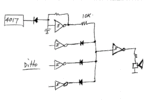
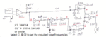
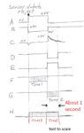
Attached are the circuit diagram, waveform diagram & a brief circuit description.

When you have this working, I'll suggest ways by which the tone can be smoothed and the output level increased.
 

Attachments

  • Ding Dong.gif
    Ding Dong.gif
    84.1 KB · Views: 87
  • Ding Dong Waveforms.gif
    Ding Dong Waveforms.gif
    63 KB · Views: 84
  • Description.txt
    1.2 KB · Views: 49

Thank you for the circuit. I'm going to read up a little more on how some things, like Diodes, work so I can understand it in theory as well as make it work on the board.

Before I start on it, I was playing with the 74HC14 and 4017 counter a little bit more. With the diode suggested before between the counter output and the Schmitt input to keep the tone from playing until its turn on the counter, and the math to figure out the desired frequency, I was able to make a pretty cool little Westminster Quarter (first quarter) chime. It goes through the notes (approx), G#, F#, E, B. I actually used the same counter I had LEDs connected to, so I have 5 red LEDs counting in sequence, then the 4 notes. Output 9 is open for a short pause before starting over. I decided for my Ding Dong sound, I'll use G# and E, and I already have the resistor values figured out for that. I'll post how the circuit above goes :)
 

How did you change the frequency of the oscillator to cover all of those notes?

---------- Post added at 03:21 ---------- Previous post was at 03:13 ----------

I just tried those notes on my electronic organ.

G#, F#, E, B did not sound right.

G#, E, F#, B sounded more like it.
 

Westminster Quarters has 4 different notes, in 5 different orders. The order of notes are:
(1) G#, F#, E, B
(2) E, G#, F#, B
(3) E, F#, G#, E
(4) G#, E, F#, B
(5) B, F#, G#, E

On the first quarter (15 past the hour), it plays: 1
On the second quarter (30 past the hour), it plays: 2, 3
On the third quarter (45 past the hour), it plays: 4, 5, 1
On the fourth quarter (on the hour), it plays: 2, 3, 4, 5 then bongs for how many hours it is.

Your order is the start of the third quarter, which I agree sound more familiar, but in my messing around I went with the first quarter because it only plays the notes once. :D

As for the frequencies, I looked up the Hertz frequencies of the above notes and found:
B3: 246.942 Hz
E4: 329.628 Hz
F#4:369.994 Hz
G#4:415.305 Hz

Using the formula F = 1 / (1.7 R C) and given that C is going to be 0.1 uF (due to my limited supply), my formula for finding R is:
R = (1 / (1.7 * 0.1 F)) * 1000
or R = (1 / 0.17 F)) * 1000
that gives me the R value in Kohm.

I rounded up and used resistor values of:
B (246.942 Hz) = 24K
E (329.628 Hz) = 18K
F# (369.994 Hz) = 16K
G# (415.305 Hz) = 15K

The math for the G# actually came to needing 14.16K so I tried a 13K and 1.6K in series (14.6K) but it was too high and 15K sounded better.

For the "Ding Dong" I'll use B and F#.

And after typing all this out, I re-read your question and I think the answer you were probably looking for is: I used 1 Schmitt gate (with a 1uF cap and 68K resistor) for the timing to the 4017. And then I used 4 other Schmitt gates for the 4 different notes, connected to 4 outputs (5-9) of the 4017 with diodes.
 

Thanks, I'll try those on the organ later.

I've attached a suggestion of how you can combine the tones using a resistor/diode AND gate.

I assume that you were combining them with resistors on the speaker side.

That way, there is always current through the speaker even when no tones are playing.

This way, the current is 0 since the output of the speaker driving Schmitt is low.

BTW, an alternative RC for the timing oscillator would be 0.1 uF and 680 k.
 

Attachments

  • Combining tones.gif
    Combining tones.gif
    21.1 KB · Views: 70

I assume that you were combining them with resistors on the speaker side.

Yup, I was. Each output to a resistor then all tied in to the speaker +.

Why would there be current to the speaker when it's not making a sound? If the 4 Schmitts aren't triggered to oscillate, wouldn't the current to the speaker be low, or 0?

BTW, an alternative RC for the timing oscillator would be 0.1 uF and 680 k.

Is there a difference between 1 uF and 68 K and 0.1 uF and 680 K? I mean, the math makes them equal, but is there a difference? Or just another way to do the same thing?

---------- Post added at 23:36 ---------- Previous post was at 22:21 ----------

I just finished assembling the circuit, and after connecting the sensor to the voltage comparator (LM393) and testing it, it works. 0.039v with the sensor pointed to the ceiling. 5.000v when I wave my hand over it. I have the sensitivity set to 0.4v, which is roughly 24" (60cm) away from the sensor.

I then made all the connections for the 74HC14. Double checked it. Applied power. The sound comes out fast and quiet when I wave my hand over the sensor. It sounds like it's oscillating quickly between both frequencies, even when I hold my hand over it, and it's real quiet. I checked the voltage on the output of the voltage comparator and it will only climb to 0.893v when I put my hand over it. I assume it's this too low voltage that's making the Schmitt not function properly.

Why would the voltage comparator not be putting out the full 5v? and how can I convince it to do its job properly?

On my breadboard, I have my battery connected to the Input pin of the LM7805. The Gnd goes to the Gnd rail of the breadboard. The 5v Output goes to A) the resistor/pot combo for the comparator (the - Input on pin 6), B) the Vcc of the LM393 Comparator and C) a 10K pullup resistor to the output of the Comparator.

Additionally, the Comparator has pin 4 connected to Gnd. Pin 5 is my sensor (the + input). Pin 7, the output, is to the Power rail of the breadboard. The Vcc and Gnd connections for the oscillator are off the power rails on the breadboard.
 

Yup, I was. Each output to a resistor then all tied in to the speaker +.

Why would there be current to the speaker when it's not making a sound? If the 4 Schmitts aren't triggered to oscillate, wouldn't the current to the speaker be low, or 0?

When all 4017 outputs are low, the outputs of the 4 Schmitts are high. Therefore, they are driving current through the speaker.

The speaker only makes a sound when the current is CHANGING. Feel the cone when you apply power, you should feel it move forward or backward (depending on how the coil is wound) and it will remain in that position until the power is turned off or you start the tones.


Is there a difference between 1 uF and 68 K and 0.1 uF and 680 K? I mean, the math makes them equal, but is there a difference? Or just another way to do the same thing?
Yes that's right. But you will use a bit less energy since the resistor is higher. It is marginal. The other factor is that 0.1 uF is smaller & cheaper than 1 uF.

---------- Post added at 23:36 ---------- Previous post was at 22:21 ----------

I just finished assembling the circuit, and after connecting the sensor to the voltage comparator (LM393) and testing it, it works. 0.039v with the sensor pointed to the ceiling. 5.000v when I wave my hand over it. I have the sensitivity set to 0.4v, which is roughly 24" (60cm) away from the sensor.

I then made all the connections for the 74HC14. Double checked it. Applied power. The sound comes out fast and quiet when I wave my hand over the sensor. It sounds like it's oscillating quickly between both frequencies, even when I hold my hand over it, and it's real quiet. I checked the voltage on the output of the voltage comparator and it will only climb to 0.893v when I put my hand over it. I assume it's this too low voltage that's making the Schmitt not function properly. Yes, the Schmitt needs about 3 Volt to trigger and then about 1 Volt to "untrigger".

Why would the voltage comparator not be putting out the full 5v? and how can I convince it to do its job properly? If I understand what you said above, the comparitor works properly when the Schmitt is not connected, but can only rise to 0.893 V when the Schmitt is connected.

If so, then this means that something is loading the output of the comparitor. What happens if you unplug the Schmitt IC and leave everything else unchanged?


On my breadboard, I have my battery connected to the Input pin of the LM7805. The Gnd goes to the Gnd rail of the breadboard. The 5v Output goes to A) the resistor/pot combo for the comparator (the - Input on pin 6), B) the Vcc of the LM393 Comparator and C) a 10K pullup resistor to the output of the Comparator. This looks right so far, but you have not mentioned Vcc to the Schmitt.

Additionally, the Comparator has pin 4 connected to Gnd. Pin 5 is my sensor (the + input). Pin 7, the output, is to the Power rail of the breadboard. The Vcc and Gnd connections for the oscillator are off the power rails on the breadboard. Ah, I take back what I said above. However, do you mean that the Schmitt Vcc is connected to 5 Volt?
And I assume you have the pot connected to the - input.

What happens if you disconnect the comparitor and apply 5 Volt to point A in my diagram?

From this distance, I can only guess what is happening.

It sounds to me that the Schmitt does not have 5 Volt on its pin 14.

Alternatively, one of the Schmitt inputs may have been damaged by a static discharge. Do you know about the anti static precautions that you should follow when handling MOS devices?

So I suggest that you do the checks that I suggested above and let me know how you go.
 
Last edited:

Here are the results of my tests:

If I physically remove the Schmitt, leaving all the connections, the comparator climbs to 4.998 volts when I move my hand in front of the sensor.

However, do you mean that the Schmitt Vcc is connected to 5 Volt?
Assuming the comparator puts out 5 volts, yes the Schmitt is connected to 5 volts. The comparator feeds the power rail on the breadboard, and the Schmitt Vcc is connected to that.

Leaving the Sensor and voltage comparator attached, and disconnecting the Schmitt Vcc pin 14 from the power rail, I get about 1.5 v from the comparator when I move my hand in front of the sensor. I also get a noise coming out of the speaker when I put my hand over the sensor. (more on the noise below)

Leaving Pin 14 disconnected and then disconnecting the 220 ohm resistor from power (the one that goes to D1), I still get 1.5 volts when putting my hand over the sensor, and noise.

Reconnecting the 220 ohm resistor, and disconnecting the jumper from the power rail to A, the comparator climbs steadily to 4.998 volts when I put my hand over the sensor.

Is that where the problem is? Having A connected to the 5 volt output of the comparator?

The pot is connected to the - input of the comparator.

If bypass the comparator by removing the comparator output from the power rail, and feed 5 volts to the power rail straight out of the 7805, I get a louder (and I think higher pitched) version of the noise I get with the comparator in place. The noise sounds like, and I can't confirm this, my two notes (E and G#) playing one after the other continuously and very fast. I just know that it doesn't sound like a single tone.

The Schmitt Vcc is receiving 5 volts at this point, but still isn't operating as it should.

I'm aware of the dangers of static electricity and I take the precautions I can. We generally don't get much, if any, static electricity in my house. The weather outside is damp, not dry, these days. But I also try not to handle the ICs because I'm paranoid. I use an IC puller to pull them out and put them in place.

I swapped out the 74HC14 for a second one I bought at the same time and I get the same results. I could try putting a capacitor and resistor on each gate to test them individually, but I don't think that's the problem.

I hope this helps your long distance trouble shooting and if there's anything else I can test, let me know. I have a multimeter, but no scope.
 

Here are the results of my tests:

If I physically remove the Schmitt, leaving all the connections, the comparator climbs to 4.998 volts when I move my hand in front of the sensor. So what ever was loading it has been disconnected.

BTW, 4.998 Volt is near enough to 5 Volt, so I would just refer to it as 5 Volt.


Assuming the comparator puts out 5 volts, yes the Schmitt is connected to 5 volts. The comparator feeds the power rail on the breadboard, and the Schmitt Vcc is connected to that.

By "power rail" I assume the 5 Volt line. Is this correct?

Leaving the Sensor and voltage comparator attached, and disconnecting the Schmitt Vcc pin 14 from the power rail, I get about 1.5 v from the comparator when I move my hand in front of the sensor. I also get a noise coming out of the speaker when I put my hand over the sensor. (more on the noise below) You said in your earlier post, that you measured 0.893 Volt at the comparitor output with the circuit as it is in my diagram. So by disconnecting Vcc to the Schmitt, the voltage has increased by about 0.6 Volt.

Leaving Pin 14 disconnected and then disconnecting the 220 ohm resistor from power (the one that goes to D1), I still get 1.5 volts when putting my hand over the sensor, and noise.

Therefore, the mysterious load is not going via the 220 Ohm.

Reconnecting the 220 ohm resistor, and disconnecting the jumper from the power rail to A, the comparator climbs steadily to 4.998 volts when I put my hand over the sensor.

By "power rail" I assume that you still mean the 5 Volt line. I did not know that you had connected A to the 5 V.

Is that where the problem is? Having A connected to the 5 volt output of the comparator?

The pot is connected to the - input of the comparator.

If bypass the comparator by removing the comparator output from the power rail, and feed 5 volts to the power rail straight out of the 7805, I get a louder (and I think higher pitched) version of the noise I get with the comparator in place.
I'm still confused by "power rail". The comparitor output is connected to the 10k resistor and to A.

The noise sounds like, and I can't confirm this, my two notes (E and G#) playing one after the other continuously and very fast. I just know that it doesn't sound like a single tone.

The Schmitt Vcc is receiving 5 volts at this point, but still isn't operating as it should.

See below.

I'm aware of the dangers of static electricity and I take the precautions I can. We generally don't get much, if any, static electricity in my house. The weather outside is damp, not dry, these days. But I also try not to handle the ICs because I'm paranoid. I use an IC puller to pull them out and put them in place.

I swapped out the 74HC14 for a second one I bought at the same time and I get the same results. I could try putting a capacitor and resistor on each gate to test them individually, but I don't think that's the problem.

I hope this helps your long distance trouble shooting and if there's anything else I can test, let me know. I have a multimeter, but no scope.
What happens if you connect every thing as in my circuit diagram and then remove the Comparitor IC? The voltage at A should rise to 5 Volt and the first chime should start.

Then connect A to Gnd, and the second chime should start.
 

By "Power Rail" I mean the + and - lines on the sides of the breadboard (or protoboard). The - is connected to the Gnd of the battery. The + is the output of voltage comparator. Using long jumpers, I'm joining the + on the left and right sides together, as well as, separately, the - on the left and right sides. The connections run the full length of the board as well (they aren't broken in the middle like some breadboards I've seen). I just checked Wikipedia and what I call the "Power Rails" are the "Bus Strips", for Ground and Supply Voltage.

By "power rail" I assume that you still mean the 5 Volt line. I did not know that you had connected A to the 5 V.
A is connected to the output of the voltage comparator. In this case, because the output of the comparator is connected to the + side of the Bus Strip, it should be receiving 5 V. The only time the + side of the Bus strip has power is when the comparator detects more than 0.4v. That means that pin 14 of the Schmitt and "A" don't receive power.

My 9V battery is connected to the Gnd Bus Strip, and the input of the 7805. The 7805 has the Gnd connected to the Gnd Bus Strip, and the output connected to the voltage comparator Vcc, and through the resistor and pot to the - input. The output of the comparator is to the Supply Bus Strip.

I will try giving the Schmitt Vcc +5 V directly (and not switched on from the comparator), then take the comparator output directly to A instead of through the Bus Strip. Maybe that's the problem?

Thank you for your patience :)
 

By "Power Rail" I mean the + and - lines on the sides of the breadboard (or protoboard). The - is connected to the Gnd of the battery. The + is the output of voltage comparator.
The Vcc {pin 8} of the comparitor should be connected to the +5 Volt rail, and pin 4 to the Gnd rail.

Pin 14 of the Schmitt should be connected to the +5 Volt rail also and pin 7 to the Gnd rail.

Using long jumpers, I'm joining the + on the left and right sides together, as well as, separately, the - on the left and right sides. The connections run the full length of the board as well (they aren't broken in the middle like some breadboards I've seen). I just checked Wikipedia and what I call the "Power Rails" are the "Bus Strips", for Ground and Supply Voltage.


A is connected to the output of the voltage comparator. Correct.

In this case, because the output of the comparator is connected to the + side of the Bus Strip, it should be receiving 5 V. The only time the + side of the Bus strip has power is when the comparator detects more than 0.4v. That means that pin 14 of the Schmitt and "A" don't receive power.

This is your problem.

My 9V battery is connected to the Gnd Bus Strip, and the input of the 7805. The 7805 has the Gnd connected to the Gnd Bus Strip, and the output connected to the voltage comparator Vcc, and through the resistor and pot to the - input. The output of the comparator is to the Supply Bus Strip.

I will try giving the Schmitt Vcc +5 V directly (and not switched on from the comparator), then take the comparator output directly to A instead of through the Bus Strip. Maybe that's the problem?

yes!

Thank you for your patience :)

Sorry, I neglected to draw the Vcc & Gnd connections on my circuit. The 74HC must be permanently connected to the +5 Volt and Gnd lines.
 
Last edited:

Okay, my new setup is:

External power (9 v battery, or 12 v wall wart) going to 7805 + input, ground to ground bus strip. 5 v output from 7805 going to Bus Strip +.

That provides 5v power to all the components: Sensor, LM393, and 74HC14, and they now have constant power :)

The rest of the circuit is assembled as it should be. I think.

When I have the circuit assembled as per the diagram, I get a constant low note from the speaker, like a putt-putt-putt-putt of a race car engine. The comparator is putting out 0.05 volts. Wave my hand over the sensor, the comparator puts out 5 volts, I get the high note, remove my hand and it's back to the putt-putt-putt. The high note is not a clean note, either. It pulses, or is on and off very quickly. Like a fast doo-doo-doo-doo

If I remove the 10k pullup resistor, I no longer get the putt-putt-putt sound. The comparator is putting out 0.025 volt. I put my hand in front of the sensor, the comparator puts out 2.3 volts, the pulsing high note plays, I remove my hand and a pulsing low note plays for a second and stops.

I thought the problem with the pulsing notes might be because the Schmitt isn't getting a full 5v from the comparator, so I connected A directly to the 5 v bus strip. I get the pulsing high note. I remove A from the 5v bus strip and I get a pulsing low note for about a second and it stops.

I'm also getting about 2.5 volt from H when the tone is making noise.
 

Okay, my new setup is:

External power (9 v battery, or 12 v wall wart) going to 7805 + input, ground to ground bus strip. 5 v output from 7805 going to Bus Strip +.

That provides 5v power to all the components: Sensor, LM393, and 74HC14, and they now have constant power :)

The rest of the circuit is assembled as it should be. I think.

When I have the circuit assembled as per the diagram, I get a constant low note from the speaker, like a putt-putt-putt-putt of a race car engine. This sounds like what is called "motor boating"

It is usually due to positive feedback via the supply line.

Do you have capacitors on both sides of the Voltage Regulator?


The comparator is putting out 0.05 volts. Wave my hand over the sensor, the comparator puts out 5 volts, I get the high note, remove my hand and it's back to the putt-putt-putt. The high note is not a clean note, either. It pulses, or is on and off very quickly. Like a fast doo-doo-doo-doo

If I remove the 10k pullup resistor, I no longer get the putt-putt-putt sound. The comparator is putting out 0.025 volt. I put my hand in front of the sensor, the comparator puts out 2.3 volts, the pulsing high note plays, I remove my hand and a pulsing low note plays for a second and stops.

I thought the problem with the pulsing notes might be because the Schmitt isn't getting a full 5v from the comparator, so I connected A directly to the 5 v bus strip. I get the pulsing high note. I remove A from the 5v bus strip and I get a pulsing low note for about a second and it stops.

I'm also getting about 2.5 volt from H when the tone is making noise.
I presume that your multimeter is reading the average voltage of the square wave signal. The duty cycle will be about 50% and the signal is switching between 0 Volt and 5 Volt, therefore the average is about 2.5 Volt.
You also need a ceramic capacitor in the range 10 nF to 100 nF as a high frequency bypass. This prevents odd effects due to coupling through the supply line.

One capacitor per 2 ICs is usually sufficient, connected as close as possible to the ICs.

Here is a scan from the data section of the Dick Smith catalogue. It gives you some basic info about voltage regulators.

Also have a look at page 1 of the attached 7805 data sheet. It shows the bypass capacitors that are required for the 7805 Regulator.
 

Attachments

  • DSE data.jpg
    DSE data.jpg
    513.8 KB · Views: 58
  • 78xx reg.zip
    174.7 KB · Views: 45
Last edited:

I didn't have bypass capacitors, but I do now. My supply is limited, so I put a 0.1uF from the Input of the LM7805 to Gnd, and another from the Output to Gnd. I also used 0.1 uF capacitors from the Vcc pin to Gnd on the LM393 and 74HC14 (I used the Bus Strip for the Gnd connections, btw). I think that's what you mean for a high frequency bypass?

I noticed in the datasheet that a 0.33uF capacitor is used on the Input of the 7805. The closest I have to that is a 0.22uF, so I tried that and no difference.

I still get the motor boating with the pullup resistor in place, and with or without the resistor the high tone still .. well, I guess it still motorboats, too, just at a higher frequency.
 

I didn't have bypass capacitors, but I do now. My supply is limited, so I put a 0.1uF from the Input of the LM7805 to Gnd, and another from the Output to Gnd. I also used 0.1 uF capacitors from the Vcc pin to Gnd on the LM393 and 74HC14 (I used the Bus Strip for the Gnd connections, btw). I think that's what you mean for a high frequency bypass?

Yes

I noticed in the datasheet that a 0.33uF capacitor is used on the Input of the 7805. The closest I have to that is a 0.22uF, so I tried that and no difference.

Do you have another 0.1 uF? If so connect it in parallel with the 0,22. That wil;l; give you about 0.32 uF which will be near enough.

I still get the motor boating with the pullup resistor in place, and with or without the resistor the high tone still .. well, I guess it still motorboats, too, just at a higher frequency. See below.
I'll have to post this and re-read your earlier posts.

---------- Post added at 21:58 ---------- Previous post was at 21:31 ----------

Your problem appears to be associated with the comparitor IC1.

I suggest you disconnect the output of IC1 and leave the 10 k connected.

Apply a Gnd to A and then turn the power on. It may sound tones initially until it becomes stable but then it should be silent.

Then remove the gnd from A and tone F should sound.

Re-apply the Gnd to A and tone G should sound for about 1 sec.

Then there should be silence again.

By G & F I mean the points on the circuit, not musical notes.
 

I've done that and I get the same results, with the exception of the motor boating while the resistor is connected.

I recorded the sound that I'm getting, if it helps.
**broken link removed**
 

Yes I can hear the modulation.

Did you see the second part of my previous post?

Was the recording done while IC1 was disconnected?

If so, what happens if you turn your pot up to its maximum, ie. at the positive end?

I know it will not detect the sensor correctly if you do this, but I think IC1 is oscillating, so doing the above should stop it.

If this is the case, then I have further suggestions.

Alternatively, just unplug IC1
 

IC1 was disconnected when I did the recording. Just the 10k pull up resistor. So, without IC1, the sensor isn't active either.

I just unplugged IC1 and the modulation still occurs.
 

I realised what the problem is while I was doing something else.

You need an electrolytic bypass capacitor between the +5 Volt and 0 Volt lines.

The smaller caps provide high frequency bypassing and the electros provide low freq.

The electros have too much impedence at high frequencies, so you need both.

You will need at least 100 uF. However, even if you don't have one that big (or bigger) on hand, then even 22 uF would help.

The IC1 may be oscillating also, but that is another issue.

If it is happening, the electro may solve it.

If not we will have to introduce some hystersis. But ignore that possibility for the moment.
 

Status
Not open for further replies.

Part and Inventory Search

Welcome to EDABoard.com

Sponsor

Back
Top