Tiago Santos
Newbie level 3
This sounds like the perfect job for a PIC10
I'd also try some low chips from freescale.
Follow along with the video below to see how to install our site as a web app on your home screen.
Note: This feature may not be available in some browsers.
This sounds like the perfect job for a PIC10
Thank you very much! I'll get started on assembling that tomorrow after I pick up a couple resistors and capacitors for it. I'll let you know how I make out with it.
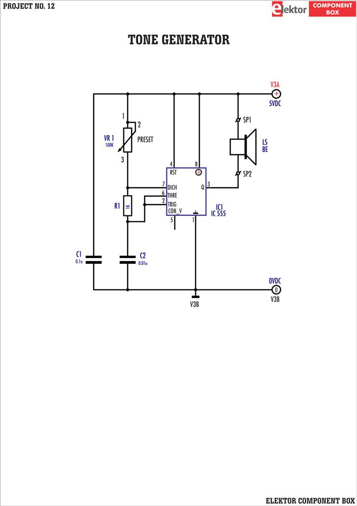
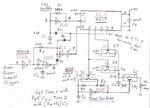
@ljcox: Regarding the tone oscillator in the latest drawing, you wrote "Set tone 1 with Rb c3, Tone 2 with (Ra+Rb)C3" Just for clarification, the two tones I want are G# and E (for High and Low, respectively). Using the resistor values I posted for the notes in Post #24, that would be G#: 15 K and E: 18 K. The C value I used is 0.1 uF.
Would I use a 15K for Rb and 3K for Ra in this case?