Continue to Site

Welcome to EDAboard.com

Welcome to our site! EDAboard.com is an international Electronics Discussion Forum focused on EDA software, circuits, schematics, books, theory, papers, asic, pld, 8051, DSP, Network, RF, Analog Design, PCB, Service Manuals... and a whole lot more! To participate you need to register. Registration is free. Click here to register now.

Proximity Sensor Help

Status
Not open for further replies.

Kolero

Member level 1
Joined
Dec 10, 2010
Messages
41
Helped
0
Reputation
0
Reaction score
0
Trophy points
1,286
Location
Vancouver, BC
Activity points
1,795
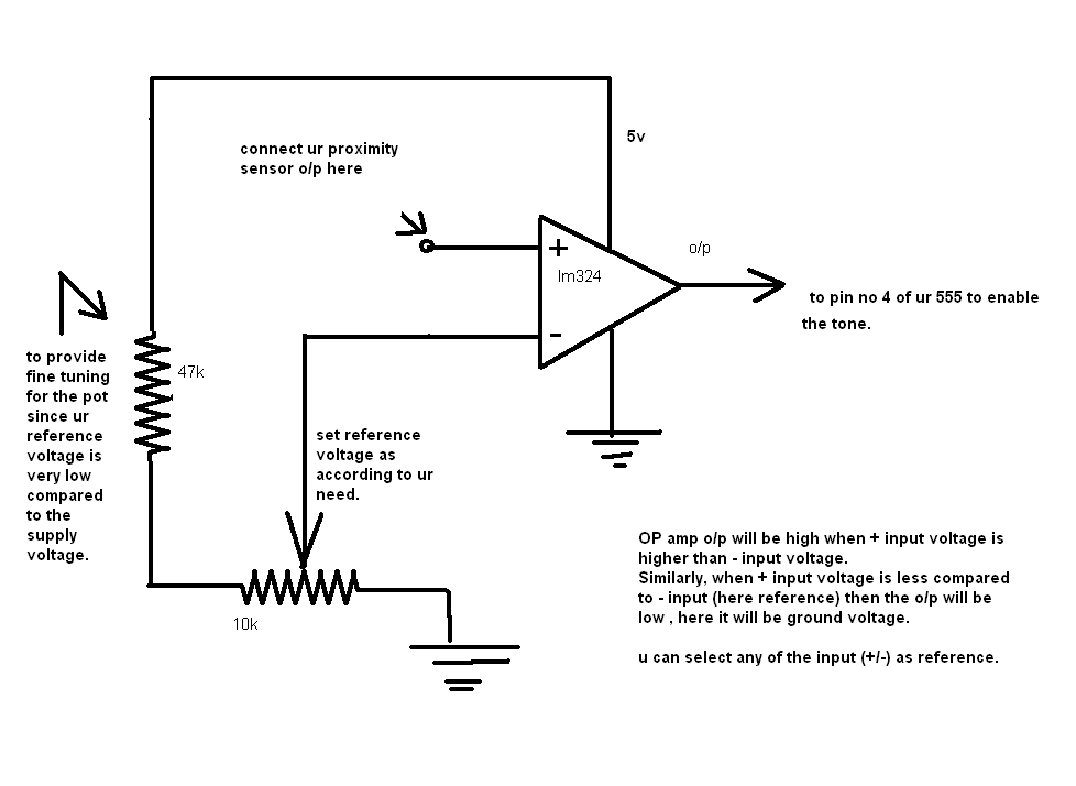
I have two circuits: One is a pair of 555 timers wired to a basic alarm type sound, powered by a 9v battery. The second is simply a Sharp Proximity Sensor GP2Y0A21, powered by 4.8v.

How can I make the proximity sensor trigger the alarm circuit when the proximity sensor reaches 0.4 volts or higher. The closer an object is to the sensor, the higher the output voltage, but I want it to trigger at 0.4, or 0.5 volts, when an object is 2 feet from the sensor, or closer.

If more details are needed, please let me know. It's been about 16 years since I took Electronics in high school, and I seem to have forgotten a couple things along the way.
 

u can use an opamp comparator for this purpose....there set the reference voltage as 0.4 using resistor voltage divider, better use a pot...
 
Last edited:

Thanks for the reply! I looked up a couple sites that explains how Op Amps work as comparators and I'm trying to understand how it works.. or how to connect it to my circuit.

As I see it, the Op Amp would take the reference voltage in the + input. I would use a trim pot to fine tune it to 0.4v.

I would take the output from my proximity sensor and connect it to the - input.

I would connect the +V Supply to 9V, and -V Supply to negative.

When the proximity sensor voltage reaches the reference voltage, or higher, the comparator will output 9v and that will then power the alarm circuit. Is this right?

Will the Op Amp consume much power when the proximity sensor output is below the reference voltage?
 

u r right...But if u want a high voltage as o/p when ur proximity sensor voltage exceeds the reference voltage, then u should give reference voltage to - input of the o/p amp. ...actually o/p amp will not consume much power because the reference and input voltages will not make much current through the o/p amp. Ideally an O/P amp input
impedance is infinity and o/p impedance is zero.
70_1292063179.png
 
  • Like
Reactions: Kolero

    Kolero

    Points: 2
    Helpful Answer Positive Rating
Thank you for the schematic, that is very helpful. One more questions to make sure that I understand this:

In your drawing, you have 5v supply voltage to the op amp. Would the op amp output 5v? If I connect the 9v to the supply voltage, will it then ouput 9v to the 555 timer?

What's the difference between using an LM324 OpAmp and a LM339 Voltage Comparator?

EDIT: I bought the LM339 today and I can't seem to make it work. I connected it as per your schematic, and I trimmed the pot to give 0.4v. I even raised the reference voltage to 0.8v in case 0.4 was too low.

Using my multimeter, I tested the voltage on various pins. The reference voltage is 0.8v. The voltage from the proximity sensor sits at 0.2v until I move my hand over it and it climbs as high as 3.1v. Easily passing the 0.8 threshold I set. The output from the comparator goes from 0.002v to 0.029v when the voltage from the proximity sensor passes 0.8v.

My power is coming from a 9v battery (for now. I will use an AC Adaptor when I have everything running). I'm using an LM7805 to convert the 9v to 5v for the proximity sensor. I'm using the 9v from the battery for the supply (pin 3) of the LM339 and the clean 5v from the 7805 for the resistors for the reference voltage.

Could the comparator be a dud? Is there a way to test it?
 
Last edited:

I think you had tested only one of the four comparators in the ic...is it? If so then test other three comparators also. If you are still not getting a result then i think your ic may be bad...
Also pls verify the circuit diagram ...pin diagram is below..
CircuitSpecLM339Pinout.gif
 

Yep, that's the same pinout I have. I tried all 4 and nothing. I'll pick up a couple more ICs on Monday.
 

I bought two new LM393 (dual comparator). I figured I wasn't going to use all 4 in a Quad. I connected the unused inputs to ground, then added a pullup resistor to the output and I'm getting the full output voltage. Thank you for your help!
 

yes, u can use 10k resistor....
1>If u use very low resistor then it will increase the power loss.
2>If u r connecting a low impedance load at the o/p of comparator and if the pull up resistor is very very high then the maximum voltage at the o/p will be too low.
3>In ur application the o/p is to be connected to the reset pin of 555 , it doesn't take much current ie the impedence is high. So u can connect a high resistance (10k ) and u can even test with resistors >10k .
 

Status
Not open for further replies.

Part and Inventory Search

Welcome to EDABoard.com

Sponsor

Back
Top