Continue to Site

Welcome to EDAboard.com

Welcome to our site! EDAboard.com is an international Electronics Discussion Forum focused on EDA software, circuits, schematics, books, theory, papers, asic, pld, 8051, DSP, Network, RF, Analog Design, PCB, Service Manuals... and a whole lot more! To participate you need to register. Registration is free. Click here to register now.

Horn Antenna Excitation in HFSS

Status
Not open for further replies.

dlock

Junior Member level 2
Joined
Dec 6, 2010
Messages
23
Helped
2
Reputation
4
Reaction score
2
Trophy points
1,283
Activity points
1,433
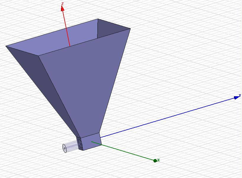
I am designing a Horn antenna using coaxial n-type connector for feed.The design is such that the aperture of antenna opens in the z-direction. Now i wanted to apply the coaxial feed from z direction to the waveguide.Someone told me that i should not apply feed in z-direction when horn aperture is also oriented in z-direction cause for Horn antenna Ez=0, so the antenna wont be directional...is it so??Is there any problem in feeding above mentioned antenna from z-direction?
 

Hi,

I do not know what is the exact geometry of your antenna in 'HFSS'. Post it here and only then i can answer your question.

/SC
 

In the attached figure, you are feeding it from the -ve Yaxis. It is correct.
/SC
 
First separate the coax feed from the horn. Model them separately at least at first.

We assume you have set up the design boundaries, air box, etc.

You excite the horn by selecting the waveguide end, and placing there a excitation port. At this stage you can find out all you need for the horn.
I think the port radiates both ways, but that does not matter for now, so long as you know of it. The Help examples (say for Tee or Coupler) show how to make place such ports.

Then, the design of the coax feed into a waveguide do separately. It would have the reflective cavity, or other features behind the monopole, whatever. It is excited by a voltage source this time, and the wave it makes will be advancing out of the waveguide.

Join the models together. Now you have directionality.

It is also possible to force a wave port at the horn entrance, and work the whole thing in reverse..
 
  • Like
Reactions: dlock

    dlock

    Points: 2
    Helpful Answer Positive Rating
Hi Darktrax,

I have told these things to dlock in private message as he has asked for it. I hope that uptill now he has simulated the antenna by placing the port at the bottom of waveguide end i.e at z=o !!!
 

Hi Darktrax,

I have told these things to dlock in private message as he has asked for it. I hope that uptill now he has simulated the antenna by placing the port at the bottom of waveguide end i.e at z=o !!!
Thanks sweetchoto.
I modeled my first corrugated horn internal shape by stacking a series of cylinders atop a short cone, starting at z=o. I selected all faces except the horn entry and the waveguide face, and used "Unite" to blend them all together as one. This took some work because "Select All Visible" did not seem to allow un-selecting the front and rear entries. Once many faces are selected using Ctrl-click, its easy to suddenly lose them all while panning or rotating the view!

Then I placed the excitation post at z=0.assigned the Perf-E. I put a AirBox around all, making it big enough that there was at least 3 wavelengths space to the horn.

Then, I selected all, and assigned it Perf-E, making all surfaces conductive.

After generating the solution, I used Field Overlays -> E Field -> Mag_E1
The pattern it showed was good - low sidelobes, but it showed a radiation squirt straight out the back of the excitation port. Maybe I should have put a waveguide with one of those "perfect absorber" things on it, but I did not bother.

One thing I am not sure about, is the correct way to define a circular polarized wave port. If one edits the excitation Port1 -> Properties -> Modes, then there is a checkbox for "Polarize E Field. Using it will bring the message that two modes are needed by the solver to polarize. This then forces that a second "integration line" is defined. (Getting complicated now!). Click on the second mode to define a line, and the choices are..
* New Line
* Duplicate Previous Line
------------
*Copy From Mode 1

So how does this work? Should the second integration line be at 90 degrees to the first? How is the second mode part of a circular polarized wave if the line can be simply copied from Mode 1 as part of this option anyway. :-?
 

Hi Darktrax,
You have answered your query yourself in the end. Yes in order to have a circularly polarized wave,the second integrating line should be defined at 90 degrees compared to the first. You can have two options in case of Circular polarization: RHCP(right hand circular polarization) and LHCP(Left hand circular polarization),if you will enter a phase difference of 90degree between the two lines defined along x-axis and y-axis then you will get LHCP whereas if you ll define this difference to be -90degree you will get RHCP.

I hope it is clear to you now. I am not very active these days on this forum so i have read your message quite late. Hope it solves your issue.

/SC
 

Hey, friends, I want to ask one question. I am working on corrugated horn antenna and I have many doubts regarding it's simulation in HFSS. I have come to know that I have to give 6 modes while giving excitation. Now, the problem is that my cross polarization becomes worst when I define 6 modes. But when I define only 1 mode and that is its fundamental mode by default in HFSS, it gives me lot more better cross polarization response. Please help me!!! it becomes very critical for me to solve this problem as my research review is going to be in 10th February. And I am still not getting proper results for very basic corrugated horn antenna design in HFSS. please please reply as soon as possible!!!!
 

Status
Not open for further replies.

Part and Inventory Search

Welcome to EDABoard.com

Sponsor

Back
Top