Continue to Site

Welcome to EDAboard.com

Welcome to our site! EDAboard.com is an international Electronics Discussion Forum focused on EDA software, circuits, schematics, books, theory, papers, asic, pld, 8051, DSP, Network, RF, Analog Design, PCB, Service Manuals... and a whole lot more! To participate you need to register. Registration is free. Click here to register now.

2cm thick line of signal view?

Status
Not open for further replies.

emaatta

Newbie level 4
Joined
Nov 3, 2010
Messages
6
Helped
0
Reputation
0
Reaction score
0
Trophy points
1,281
Activity points
1,337
2cm thick beam line in Iwatsu SS5711 oscilloscope

Hello,

I have a nice old oscilloscope Iwatsu SS5711.
Now I have one technical problem with it and haven't
found a right service manual for it. I found
instruction manual for model SS5710,
but unfortunately SS5710 is not similar model.
Circuit boards are different between these models.


Please help me to get just right service manual for my scope?

Also I would be very happy if I would find someone specialist to tell
me what is gone faulty in my scope as the beam line of it is very wide
and can't able to focus it.

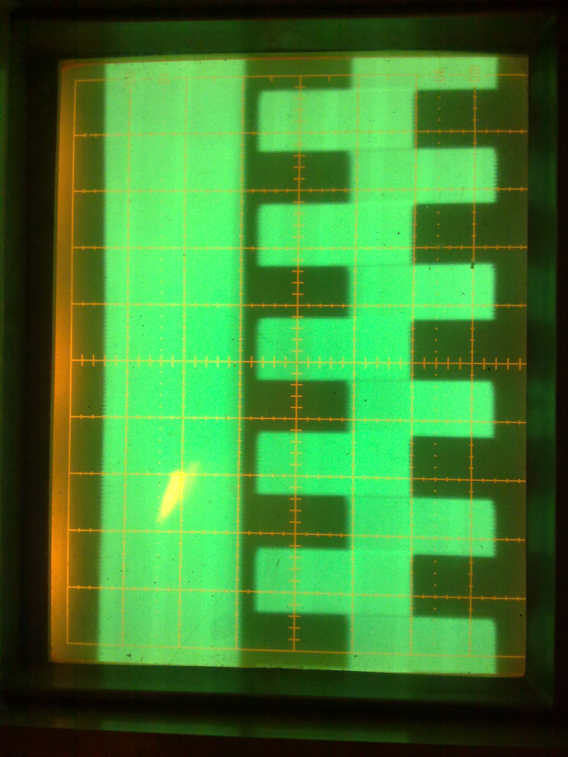
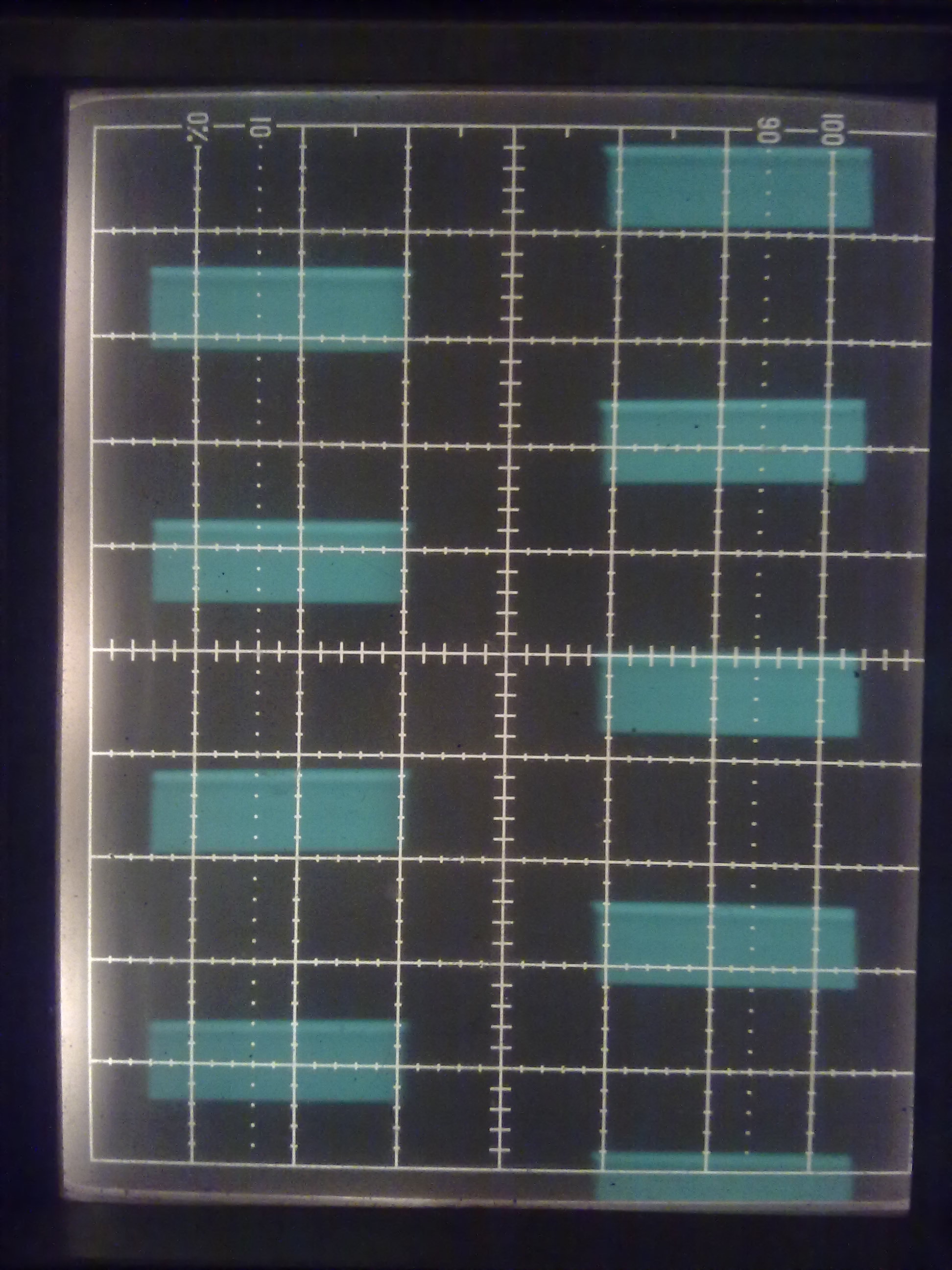
I attached here the picture of screen of the scope where the first signal is ground
signal and the second one is calibration signal. As you can see mark of the beam
is not very thin and sharp.

I have tried to tune the astig potentiometer but didn't reach better focus of the beam as figured in my view.
I measured over -400V from that astig potentiometer connector.
I don't know if this is a right value of voltage as I don't have a right circuit diagrams and measuring data values.
Regards,
Esa

271120101741.jpg
 
Last edited:

Re: 2cm thick beam line in Iwatsu SS5711 oscilloscope

Hi emaatta,
I belive, that your problem is an oscillation in Y-amlifier/wrong capacitor & GND connection...
Is it a longtime resultat or is coming with "next day switching on" pls?
K.
 

Hi karesz,

it's some kind of focus circuit problem. I can tune that line width little bit by a focus potentiometer. This problem is currently all the time and available immediately when I switch power on.
 

Hali,
No, Im other meaning...
OK, your EDA-photos resolution is so very poor, that its inpossible to see correctly for some structures in signal, but I think; it has some higher frequencies in it_ can you PM me pls a better pic?
If you hase influencies from focus setting on it, its abs. normal_ these is some independent function from the Y-amp...
Otherwise; if you can have-borrow an Oscope, do check with it pls the power supplies for humm/some RF signal etc. too!
Greetings,
K.
 

Hi,

I can't see any higher frequences in the signal. No effect if I tune time/div selection? Allways the signal seems to be the same?
Or the that inner signal shall be very very higher, so higher than my scope is out of scope :smile:

Currently I can't put another picture, but later on I try to do it.

BR,
Esa

---------- Post added at 23:18 ---------- Previous post was at 23:16 ----------

Do you karestz know where can I get the relevant repear manual for my scope or at least circuit diagrams?

- Esa
 

Hi Esa,
Im sorry, but I dont know some free sources for SM_btw Im on the finding for SS5321 SM (over some monts) :-(...
I did found SMs only for SS5702..06/5710/7606,7 & 7610,11...
In my opinion itsn`t a focus problem, I think your (RF)signal must be triggered, & we need better pic quality to check it out...
What is on the screan for a pulse frequency_is it the interanl Cal signal pls, is the amplitude on screan real from your input signal?
How was it to become with an external generator?
K.
 

Hi all,

Here is the Instruction Manual and Schematics of SS-5711:

_http://www.4shared.com/document/nx7u8-NO/SS-5711.html

I don´t know the reason,but i have problems to upload here,the site
give me this error:
"The file(s) uploaded were too large to process."

The file is only 11MB.


emaatta,hope you solve your problem.

Best regards
SDumas
 
  • Like
Reactions: karesz

    karesz

    Points: 2
    Helpful Answer Positive Rating
Hi SDumas!
Its a greet gift-tnx! :)
K.
 

Hi emaatta,

What is your progress pls, did you fixed?

Best greetings!
K.


---------- Post added at 11:03 ---------- Previous post was at 10:53 ----------

Hi karestz. Sorry about the quite a long delay of my reply :)
I just took my scope from safe and tried it again. I attached two additional pictures above.
The first one has two inputs, right side is input one connected to 1Khx CAL signal and left hand is input two as open.
This view has 1ms/Div set.
The second picture has same setupt but Time/Div has set 1 micros/Div and signal triggered to that higher frequency.
You are right karestz that there is some HF oscillating signal in my device. It seems that this HF signal has even been modulated by
lower frequency signal (1MHz?).
Have you some idea where and how could I look for the fault position from my device?
Now I have correct schematics and instrtuctions available for my device.
BR,
Esa
 
Last edited:

Hallo Esa,
On your first (topic opening) picture is a lowerfrequency (50Hz!) signal to interpret :roll:...
Did you checked the powers supply of your X&Y-Amps and all the electrolythics on the supplies pls?
Is your picture No2 not the chopper signal & some HF noise-oscillating, or even a humm "only"?
Greetings-K.
 

Hi karesz.
Thank you for you help!
I'm sorry but I did understand you first comment, what you mean?
What you mean about X&Y amps? CH1=X and CH2=Y. My chematics has CH1 and CH2 pre amplifier diagrams and then it has horizontal and vertical amplifier diagrams?
Which of them you mean? And what is the method to check those electrolythics without to remove them from boards?
Thanks and Regards, Esa.
 

Hi Esa,
I'm sorry but I did understand you first comment, what you mean?
1,
I mean your beginnings text: 27-11-10, 18:45, in the top half of the attached picture is practically a 50Hz structure to see too, also your signal hase a humm, or what is the source of them?
2,
I belive that you need a second Oscope to repair your ouw examplar, with it is the simplest way to check all powersupplies for "ceanless"!
These means; your supply voltages are (maybe) not clean DC, but loaded with some switching frequecies or mains signal too.
But BE CARE, These ARE DANGEROUS POTENTIALs & as best you must supply it over an isolation transformer too...
Otherwise you will need the borrowed Oscope for signal tracing too.
3,
For capacitors checking it exist another way too: to measure with an "in-circuir capable" ESR-meter_ in all case I belive that,
its better to take out all the old electrolythics (if an internal supply voltage isnt "clean") & replace with good new types!
You can not fix an equipment without to take-out some components...
4,
Usually we speak over "Y-amps" in case of all vertical amplifiers & the "X-Amps", or horisontal amps, are drived with the sawtooth signal(mostly dont have an external input)...
Regards, K.
 
Last edited:

Hi karesz.
Thank you for your clarification. I will try to do those checkings you proposed.
If I have checked, I will tell you my findings,

BR,
Esa
 

Status
Not open for further replies.

Part and Inventory Search

Welcome to EDABoard.com

Sponsor

Back
Top