Continue to Site

Welcome to EDAboard.com

Welcome to our site! EDAboard.com is an international Electronics Discussion Forum focused on EDA software, circuits, schematics, books, theory, papers, asic, pld, 8051, DSP, Network, RF, Analog Design, PCB, Service Manuals... and a whole lot more! To participate you need to register. Registration is free. Click here to register now.

how to design circular microstrip antenna for circular polarization

Status
Not open for further replies.

kristal

Newbie level 5
Joined
Nov 24, 2010
Messages
10
Helped
0
Reputation
0
Reaction score
0
Trophy points
1,281
Activity points
1,350
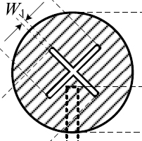
hello guys im doing my final year project.and im doing circular patch antenna for circular polarization..what seem to be the problem is that i want to know how to make it circular polarization because most of example available is for rectangular shape :cry: can anybody help me by telling feeding method or any physical dimension adjusting that can be done??any helped link also great.im using cst software
 

Circular shape patch antenna doesn't have circular polarization.
You have to cut some slots inside of the circle to get circular polarization (see the picture).

40_1290627340.jpg
 
what do you mean Circular shape patch antenna doesn't have circular polarization?i read about making the narrow slot.how to make the slot?is there any calculation?or im just cut it?how about the feeding method? very nice of u to reply my question
 

Standard circular shape patch antenna have linear polarization. So, you can get H or V polarization depending where the feeding point is placed.
Only using slots can get circular polarization. The slots dimension (length, width, etc.), depends by material used. The slots affects not only the polarization, but also the antenna impedance.
https://www.jpier.org/PIERL/pierl04/08.08050203.pdf
 
im never heard about H n V polarization...my *** its look very dificult... is there any simple way?what is advantage of circular patch compare to rectangular?..sorry for asking 2 much
 

Hello,

Have you tried to simulate the antenna? For example, this **broken link removed** separtes between right and left circular polarizations.
 
  • Like
Reactions: mkk123

    mkk123

    Points: 2
    Helpful Answer Positive Rating
Dear Vfone
Kindly, thanks for your support our quistion and I need your help for circular microstrip analysis specially for Qrad & Qc & Qd & another parameter because I have problem when calculate these values.
Thanx and your supoort
 

please your comments and solution for these equation in attachedUntitled.png
which eq OK for Qrad
your support please
 

**broken link removed** you have an example using a microstrip spiral.
ANSOFv3-Spiral.jpg
 

Status
Not open for further replies.

Part and Inventory Search

Welcome to EDABoard.com

Sponsor

Back
Top