SparkyBoy
Newbie level 5
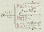
Require:
-5v 0v +5v
-12v 0v +12v
and
0v 24v
Want to use 78/79 regulators & L200 reg.
Should I use two rectifiers, one for dual rail one for single rail?
Should I use two transformers?
Can I tie all 0v together to form common ground ref.?
Will a 28v secondary voltage (for the 24v supply) over heat a 78/79 regulator?
Have lots of examples of single or dualrails supplies but not both together?
Thanks
Mark