Continue to Site

Welcome to EDAboard.com

Welcome to our site! EDAboard.com is an international Electronics Discussion Forum focused on EDA software, circuits, schematics, books, theory, papers, asic, pld, 8051, DSP, Network, RF, Analog Design, PCB, Service Manuals... and a whole lot more! To participate you need to register. Registration is free. Click here to register now.

[SOLVED] Anti rumble filter question

Status
Not open for further replies.

obrien135

Full Member level 5
Joined
Nov 10, 2009
Messages
240
Helped
5
Reputation
10
Reaction score
5
Trophy points
1,298
Location
Connecticut
Activity points
3,259
**broken link removed**

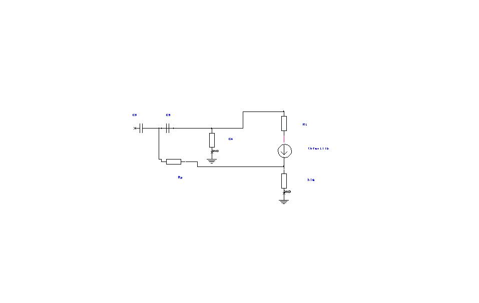
The above link shows a circuit that I am trying to redesign using a more readily accessable transister. Therefore I am try to getthe jist of how it was designed. I tried to develop a set of equations that would describe how the feedback resister affects the pole and zero placement and how it would have the effectthat they described. Maybe you could enlighten me. So far what I got for the transfer function is vo/vi=(Asc3+vbc3c4s^2)/(numerator+Asc4+A/R1+(sc4(vb-(hfe+1)Re))/R1), where A=(vb/(hie+(hfe+1)Re)+vb/(R2||R3)). Is this anywhere near right? How else can I express vb?
 

The basic filter design is near to a 2nd order butterworth filter, but by combining high- and low-pass to operate with a single buffer amplifier, the filter characteristic will be sligtly modified. The transistor type doesn't matter much, the circuit can work with any AF silicon npn.
 

But why is the R1 and the capacitor in the low pass section connected to the top of the emmittor resister instead of to ground. I know it's for feedback, but what does the feedback accomplish? Would I use the same value of R1 for any transistor , regardless of the value of Re? And isn't the input impedance too low for a phonograph cartridge to drive?
 

but what does the feedback accomplish
A second order butterworth or similar filter utilizes complex poles, to realize them without inductors, you need an actice filter respectively a feedback structure. See e.g. Active filter - Wikipedia, the free encyclopedia
Would I use the same value of R1 for any transistor?
Yes, the present emitter follower is almost unsensitive to transistor parameter variations.
And isn't the input impedance too low for a phonograph cartridge to drive?
The circuit isn't intended to be connected to a magnetic cartridge.
 

There's something about the transfer function of a closed loop feedback circuit that caused complex poles? I 've sort of seen this, but I can't remember the reason for it. I can rack my brains or search for an explaination in the library or on the internet, but maybe you could clarify it for me, if it's not too much trouble.

I took another approach andbased on the common collector having a relatively high input impedance I expressed the vo and vi in terms of the voltage on the output of C3 which I called vc3. But I couldn't figure out how to eleiminate the vc3 variaable to make it be just in terms of vo and vi ( to get the transfer function). But it knid of shows how you end up developing a second order charctoristic equation and perhaps complex poles. But I don't fully understand it. Maybe you can shed some light on this for me and also how to eliminate vc3. The equations are as follows:(vi-vc3)/(1/sc3) + (vo-vc3)/R1 = vc3/(Rp+1/sc4),

where Rp is the two base biasingresisters in parrallel,

(vo vc3)/R1 + v0/Ro)*hie + vo = vb

(Vc3 - vb)/(1/sc4) = (vo-vc3)/R1 + (vi -vc3)/(i/sc3)


I took it farther and came up withvc3 = ((vo/R1)+Vosc4+vohiesc4/Re+vohiesc4.R1) / (s(c3+c4) + 1/R4 + sc4hie/Re)

and (vi-vc3)/(1/sc3) + (vo-vc3)/R1 = vc3/(Rp+1/sc4)

How to express as vo/vi?
 
Last edited:

The equivalent circuit isn't correctly describing an emitter follower. I would use a simple ideal v=1 buffer amplifier, the difference to the actual emitter follower gain isn't important.
 
In that case, if I place it in the system prior to a high impedance input amp, couldn't I just make it a passive filter?
 

The feedback should be kept of course, basically the topology shown in the Wikipedia link.
 
Do you think that lack of an anti rumble filter is what causing my turntable to sound so distorted? It seems worse lately so it might be the needle, but I've heard of "too much overhead" caused by rumble. Can this cause clipping?
 

Status
Not open for further replies.

Part and Inventory Search

Welcome to EDABoard.com

Sponsor

Back
Top