dirace
Member level 3
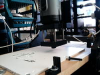
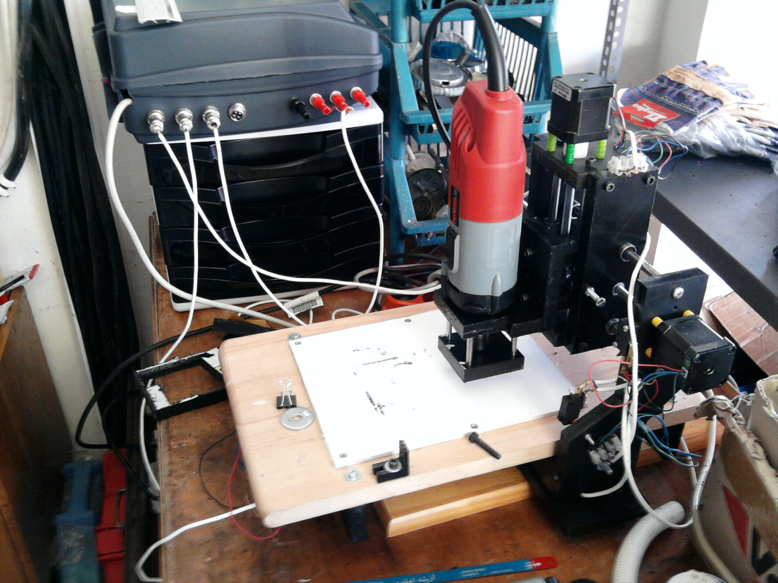
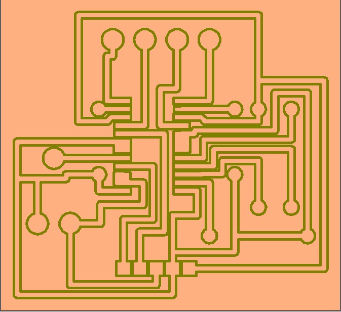
Homemade CNC for PCB
I would like to present my homemade CNC for PCB routing.
It has a floating head so height adjustment isn't critical.
It is made of plastic.
Max speed is 1400mm/sec. (It has Nema 17 steppes so there is not much torque)
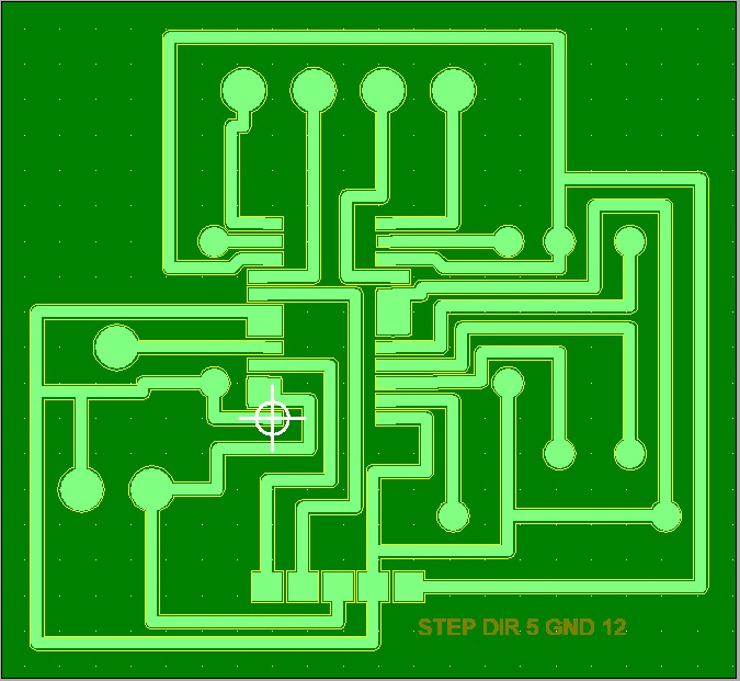
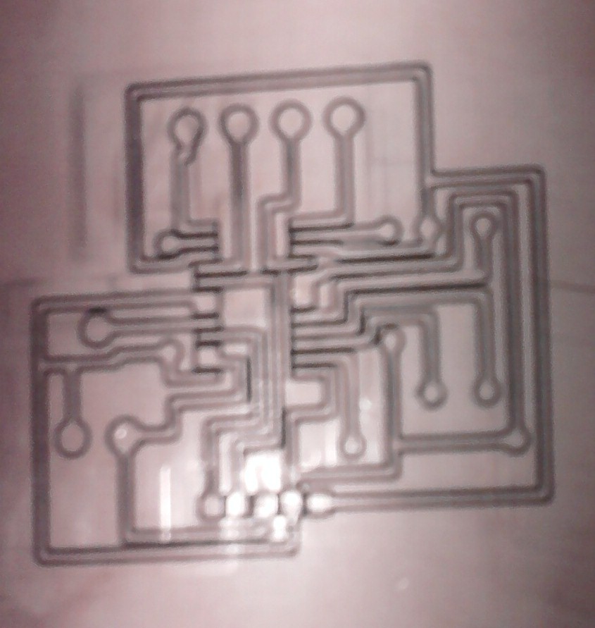
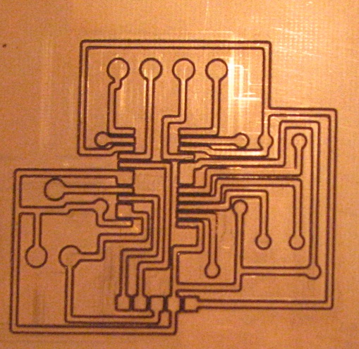
Later i will post photos of PCB I've made with it.

I would like to present my homemade CNC for PCB routing.
It has a floating head so height adjustment isn't critical.
It is made of plastic.
Max speed is 1400mm/sec. (It has Nema 17 steppes so there is not much torque)
Later i will post photos of PCB I've made with it.
")