davidwkerr
Junior Member level 2
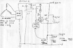
Hi All, I have designed a 240V 2KW inverter for a permanent magnet alternator. This is working okay. But, it uses 600V IGBTs and 600V driver ICs- basically I designed it for a (max) 600VDC bus. The three phase alternator puts out anything from 600VDC to around 1100VDC at a frequency between about 400 and 700Hz..
So, I thought, "no problem, I'll just design a PWM IGBT step down pre-regulator". I had a few problems with this but ended up with a semi-working unit using a 1200V IGBT switched at 10KHz by a TLP250. All drive signals look good and fast- which is part of the problem. Dissipation is in accord with calculations. It also has a soft start circuit so that there is not an almighty current inrush to the discharged capacitors at startup.
I am feeding the +ve from a three phase bridge rectifier to the collector of the IGBT. Then, the IGBT emitter goes to some series parallel capacitors. Effectively 400uF. So, I am variable PWMing the gate and have a constant output to the capacitors of 520VDC. That part works,. However, I am blowing IGBTs. After the first one, it dawned on me that I was basically switching off the alternator windings so the falling current was then inducing a big spike which of course passes through the bridge and hits the IGBT with (presumably) somewhat over the 1200 limit, destroying it. The bridge is a 1600V unit so the IGBT dies first.
No worries (I thought). I added an RC snubber across the IGBT (which is therefore also between the +ve bridge output and the +ve of the 400uF capacitor bank). Started with 550pF which is just over twice the IGBT output capacitance and a 47ohm resistor. That worked for a few minutes but then the IGBT died again (at least this time it lasted more than 1 second!) I tried 0.1uF with 47ohms and that worked fine for 10 minutes or more with nothing blowing up. I figured 10amps (max) from the alternator & 47ohms would limit me to under 500V and this seems to be the case. But the problem is that at 100V (genny 620V less 520V output on capacitors), my dissipation calculates at about 10W for the resistor and indeed this seems to be the case. I have not taken the genny to max revs, but that would bring the IGBT voltage drop to 400VDC which would increase the snubber resistor dissipation to 160W which is unsustainable.
So, I am looking for someone reading this who might have a clever suggestion on how to solve my inductive spike problem when commutating the alternator (via the bridge). I did look at various zero crossing solutions for pre-regulation using triacs and SCRs but it all got too big and complex largely because of the frequencies involved. It is frustrating to be so close with the PWMd IGBT but to be thwarted by the destructions (I've temporarily run out of suitable IGBTs so thought it time to ask for help).
I'm looking forward to any suggestions.
Thanks,
Dave,
Sydney, Australia
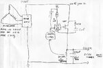