Continue to Site

Welcome to EDAboard.com

Welcome to our site! EDAboard.com is an international Electronics Discussion Forum focused on EDA software, circuits, schematics, books, theory, papers, asic, pld, 8051, DSP, Network, RF, Analog Design, PCB, Service Manuals... and a whole lot more! To participate you need to register. Registration is free. Click here to register now.

Antiparallel rectification diodes circuit

Status
Not open for further replies.

trichop

Junior Member level 3
Joined
Oct 31, 2005
Messages
31
Helped
1
Reputation
2
Reaction score
1
Trophy points
1,288
Activity points
1,580
Here is a problem that has been published in a previous thread but this time it is stated more clearly.
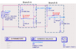
In the attached photo you'll find a snapshot of a simulation in ADS.
The circuit consists of two anti-parallel diodes.
The circuit is supposed to be the equivalent of a detector.

Now, my problem is this:
Suppose we had only one diode in the circuit (half wave rectifier), then we would measure a DC power say P.
Now with this circuit, where we have a second branch with a diode oppositely directed, I am expecting to measure a DC power 2*P (Power P from each branch).
Why?
Because I am assuming each branch rectifies its corresponding phase (either + or -) and effectively it should be something like having two half rectifiers instead of one.
However, the setup I have attached (ADS) does not prove my concept...

Do you have any ideas?
Is my train of thoughts wrong or it's the wrong simulation setup?

Thank you.
 

Attachments

  • antiparallel_diodes.png
    antiparallel_diodes.png
    174.9 KB · Views: 205

I think you measure the DC voltage between Va and Vb (i.e. Vab) and compare it with Va or Vb. Expected result is Vab = 2*Va = 2*Vb negleting the losses in the circuit. If it is so you have to exchange D2 with C2 otherwise both capacitors will be charged with the same polarity.
 

So what's the problem with the capacitors having the same polarity?
It's okay for me if Va=Vb=V.

The question was: Why I cannot measure DC power 2*P in this circuit, where P is the DC power measured if I had just one branch (half-wave rectifier)???

Any ideas?
 

Why have you put the load across the diodes rather than across the capacitors? Correct that and you might get some sensible answers.

Keith.
 

I did that but I still get the exact same results as before....
 

Hmm. I ran it without the inductors and with the resistors across the capacitors and you get equal power dissipated in each resistor. As the half wave rectification circuit is simply the same circuit with one half missing, the total power with two diodes is obviously twice that of the single diode. Mind you, I am using a Spice simulator with a transient analysis. I am not sure what sort of results you will get with a harmonic balance simulator! I don't know what your simulator will be doing, but I suspect the diodes will be turned "off". Also, you seem to be simulating at 1GHz but have put 100uH inductors in there! What are you trying to achieve?

Keith.
 
Keith, thanks once more for your contribution.

The inductors are serving as RF blockage when the circuit configuration has the resistors across the diodes.
Obviously, if we place the resistors across the capacitors no inductors are needed....

I also get equal power across the resistors but the total of them is not 2X the power of a half rectifier.
How do you know that this is two times the power of the half rectifier?
Did you also try to simulate just a standalone half wave rectifier circuit?

I really cannot understand why ADS harmonic balance shouldn't work, but anyhow I'll also try the circuit in a
second simulator.
 

Yes, I got twice the power, as I would expect. You cannot logically get anything else. If you look at your circuit you have two identical halves. If you remove one of them the power must halve and you have a half wave rectifier.

I cannot post my simulations at the moment - I will do so later.

ADS harmonic balance is for the analysis of non linear systems from the RF point of view, I think (I don't use it and never have) so I don't think it is the right tool for the job. Like an AC analysis in Spice, it probably makes some assumptions about signal size which don't turn the diodes on.

Keith.
 

You didn't yet tell your exact results? With the shown dimenioning , adding a second rectifier circuit will change the impedance matching and thus reduce the power delivered to each rectifier, that's not surprizing. The question is, if the quantitative results are correct, too.
 

I do take care of the matching.
In both cases (1) simple half wave rectifier circuit and 2)antiparallel diodes circuit) the source is
conjugately matched to the circuit.

The way I calculate the impedance of each circuit is through S-parameter simulation.
I find the impedance of the circuit and then I set the source impedance (power source) with
the corresponding conjugate impedance.
This approach should ensure that in both cases the same RF power is delivered to the circuit (source output power is fixed to 1mWatt). Right?

About the results:
- For simple half wave rectifier I get 0.2mWatt DC power.
- For the circuit presented here I get 0.125 + 0.125 = 0.25mWatt DC power.
 

In both cases (1) simple half wave rectifier circuit and 2)antiparallel diodes circuit) the source is
conjugately matched to the circuit.
If I didn't miss something, it's the first time that you mentioned different source impedances of the source in both circuits.

The way I calculate the impedance of each circuit is through S-parameter simulation.
I find the impedance of the circuit and then I set the source impedance (power source) with
the corresponding conjugate impedance.
I guess, that's the key to understand the results. S-parameters are based on a linearized small signal approximation. A rectifier is however nonlinear and correct analysis must consider this, as harmonic balance does. I don't know, how you did the S-parameter simulation, but if it won't use exactly the same signal level as the final circuit, it introduces an error. I think the only reliable method would be to vary the source impedance until you achieve maximum power delivery for each circuit.

P.S.: The exact delivered power may be different though, because the unsymmetrical case involves even harmonics that the symmetrical hasn't, and some of the generated harmonic power is dissipated in the source impedance. This make me assume less efficiency for the unsymmetrical circuit. Furthermore the different waveform also causes different diode behaviour.
 
Last edited:
Basically, I used LSSP method to extract the S-parameters. This method (in ADS) takes into consideration the input signal's strength.
Still, you have to do a couple (or more...) runs before you get the exact source impedance that conjugately matches to the circuit.
At the same time I correct the resistor's resistance so that the DC measurement circuit is also matched.

The validity of the method is also verified when I measure the power delivered from the source to the circuit.
The measured power is equal to the power source's output power.

However, as I have mentioned before the bottom line is the same:
The antiparallel circuit DC power is not 2X the DC power of the half wave rectifier circuit as intuition would suggest (at least mine...).
Depending on the source's input power, this varies from 1X up to 1.3X. It never goes higher !!!!

To FvM:
1) When you say unsymmetrical circuit you mean the one diode circuit, right?
2) What are the implications of
"...the unsymmetrical case involves even harmonics that the symmetrical hasn't, and some of the generated harmonic power is dissipated in the source impedance"
You imply we cannot be sure of the actual source's impedance?
3)You mention also:
"Furthermore the different waveform also causes different diode behavior"
Could you elaborate on that?
I understand that when a diode rectifies an already rectified waveform (from a diode of inverse polarity), the efficiency will not be the same
as if the waveform was a normal sinusoidal one.
If that's what you mean, how do you explain/support that?

Sorry for the long reply.

Thanks a lot.
 

The antiparallel circuit DC power is not 2X the DC power of the half wave rectifier circuit as intuition would suggest (at least mine...).
Depending on the source's input power, this varies from 1X up to 1.3X. It never goes higher !!!!
My intuition suggests:
- for a given source power, there's an optimal complex source impedance that achieves maximum power delivery to the load. This impedance is most likely different for the halfwave and "antiparallel" circuit variant.
- comparing both optimized cases, I expect a slightly higher efficiency for the symmetrical ("antiparallel") load, because it cancels even harmonics. A factor of 1.3 doesn't sound unlikely at first sight.
- I expect, that the efficiency can be increased by adding resonant circuits

P.S.: the result may be further complicated by the diode behaviour. Because the diodes also involve losses, there are two different criteria: maximum power delivery of the source (to diodes + load) and maximum power delivery to the load resistors. Both don't necessarily match the same source impedance.
 
Last edited:

Indeed, as expected the input impedance of each circuit we are talking about (1 diode circuit or 2 antiparallel diode circuit) is different.
Therefore, each time the power source impedance is set to the appropriate value.

Still, I cannot understand why as you say, you just expect slightly higher efficiency for the symmetrical "antiparallel" load and not 2 times better.
At least, ideally shouldn't this be the case?
What kind of resonant circuits do you mean? Something like filters?

I also disagree with your P.S. comment:
Why can't you have the the diode+loads circuit getting maximum RF power and at the same time having maximum power delivery to the load resistors?
You just have to refine the power source and the resistor resistance value many times till you get maximum values for both.
Something like an iterative method.
I never noticed having less than maximum RF power delivered to the diode+load circuit and then achieving maximum DC power delivered to the load resistor...

P.S. Do you have in mind any papers/publications that investigate similar problems?

Again, thanks a lot.
 

Why can't you have the the diode+loads circuit getting maximum RF power and at the same time having maximum power delivery to the load resistors?
I said, both don't necessarily match, not, they can't match.
If you tune all three parameter, real + reactive source impedance and load resistance, they will always match.

But I don't understand, why you expect a factor of two in delivered power between both circuits. When you optimize the source impedance, you hopefully achieve an impedance matching where only a small amount of the source power is reflected back, but because of the generated harmonics, the value can't be zero. Although the halfwave case is generating additional harmonics and a DC current, the reflected power part won't be likely as high as 50%.
 

But I don't understand, why you expect a factor of two in delivered power between both circuits...

Ok, I think we might have a misunderstanding here....
The whole talk about efficiency in not about how much RF power is delivered from the power source to the circuits.

The question is:
How much DC power does the antiparallel diode circuit deliver compared to the simple half wave rectifier circuit.
To remind my question:
My intuition would suggest that the antiparallel circuit would deliver two times more DC power to the resistor loads than the simple one diode half rectifier.

The explanation would come from the fact that the half rectifier rectifies only the positive phase and has DC output power P. In the antiparallel circuit we effectively have two half wave rectifiers and therefore we should measure DC output power 2*P, right?
 

There's no misunderstanding. I'm referring to the DC power, too.

I agree, that your explanation applies for a low frequency voltage source and no complex impedance matching. But your setting up a resonant circuit with the diode capacitance and the source inductance, that "pulls" the fundamental, so the effiency of the halfwave rectifier can be increased. You should be able to visualize the effect by watching the relation individual harmonic currents.
 

Sorry to bug again, I'd like to make sure I understand some of the the staff you write.

I agree, that your explanation applies for a low frequency voltage source and no complex impedance matching
So you say that in order to have two times more DC power delivered in the antiparallel circuit, we should have low frequencies where inductive or capacitive effects won't take place?

...that "pulls" the fundamental,...

I know this might be basic but what do you mean "pull" the fundamental?

Thanks
 

Yes, at low frequecies, the optimal source impedance would be almost real and you should get the expected factor of two in available DC power.

"Load Pulling" generally means to tune the load impedance to get maximum delivered power. In this case, I mean, that you create a series resonant circuit with the diode capacitance by making the source mostly inductive. The special trick is, that the real load impedance is only a small part of the total impedance. So the losses caused by the DC current specific to the half wave circuit are considerably reduced.
 
I keep having problems understanding you statements...

The special trick is, that the real load impedance is only a small part of the total impedance. So the losses caused by the DC current specific to the half wave circuit are considerably reduced.
So you mean that having a small real part (relatively) in the source impedance results in having less DC losses which would mean more DC output power ?

I can understand that at high frequencies where we have significant inductive or capacitive phenomena it might not be straightforward to evaluate the improvement in DC measured power of the antiparallel circuit.
Yes, we have a series resonant circuit that ensures maximum power delivery from the source to the rest of the circuit. Up to that point I still do not see why the antiparallel diode should not perform 2 times better (DC-wise).
Apparently, we might have some reflections/resonations or something between the antiparallel diodes. I think you suggested something previously about
...visualize the effect by watching the relation individual harmonic currents...
Could you elaborate a little bit more on that?

Again, thanks a lot.
 

Status
Not open for further replies.

Similar threads

Part and Inventory Search

Welcome to EDABoard.com

Sponsor

Back
Top