Continue to Site

Welcome to EDAboard.com

Welcome to our site! EDAboard.com is an international Electronics Discussion Forum focused on EDA software, circuits, schematics, books, theory, papers, asic, pld, 8051, DSP, Network, RF, Analog Design, PCB, Service Manuals... and a whole lot more! To participate you need to register. Registration is free. Click here to register now.

Please help me about AD8367

Status
Not open for further replies.

bonsevich

Newbie level 6
Joined
Apr 2, 2009
Messages
12
Helped
0
Reputation
0
Reaction score
0
Trophy points
1,281
Activity points
1,357
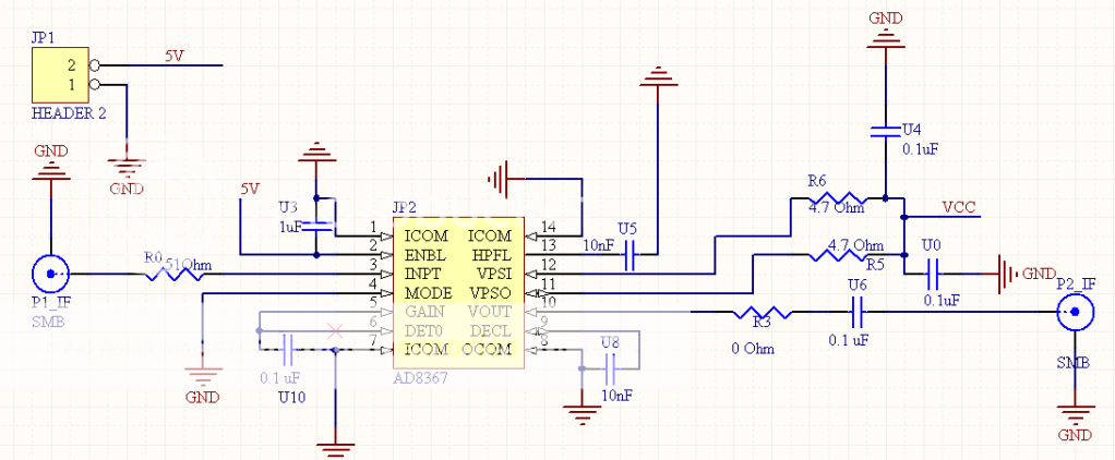
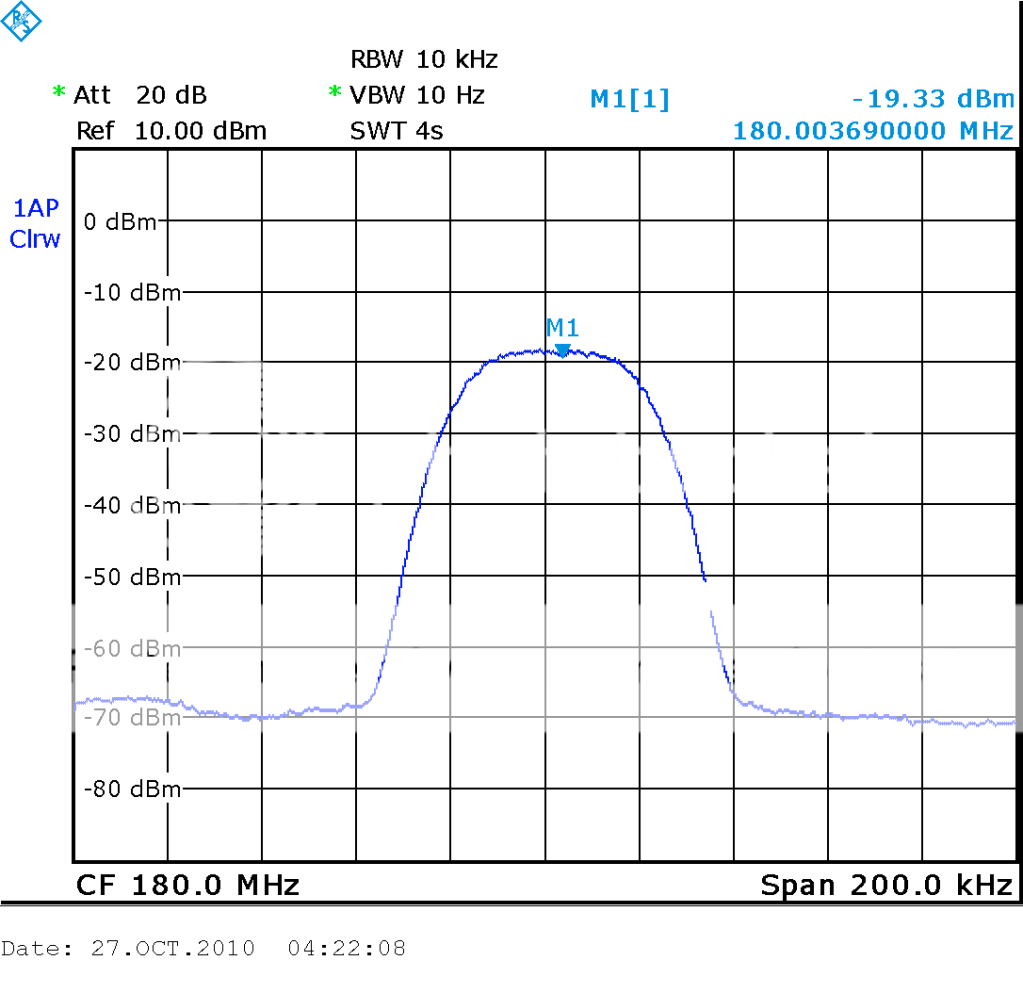
I got problems when I was implementing a AGC with AD8367. The spectrum at input here:
IN.png

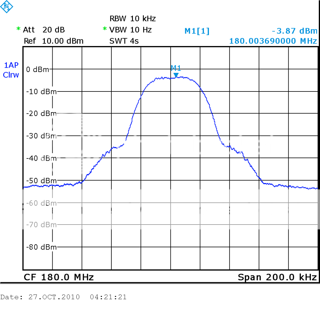
But the spetrum at output become:
OUT.png

An other problem, the level of input signal only from -20dBm to 0dBm then the level of output signal not change. If the level of input signal smaler then level of output will change (down).
Please help me resolt this problem.
Thank you very much
 

It semms that your IM3 has only -30dBc.
And your AGC loop maybe hace problem, that P1dB is too small and AGC Gain is too high. The P1dB is only about +8dBm, and the max gain can reach 42dB, so if your AGC loop set the maximum gain, then input from -20dBm to 0 dBm the output can't change.
And what's your voltage supply to AD8367? The P1dB varies from the supply voltage, if the supply voltage is only 2.5V, the P1dB is only -7dBm. Try to make correct bias for AD8367.
Good luck.
 
Thanks very much, tony_lth. The supply voltage was 5V. I tried some capacitors in AGC loop. But this is the best that I have. Here is my schematic. The schematic from datasheet is not ok. This is my schematic for that result:
SCHEMATIC_AGC-2.png

Can you show me how to improve it?
 

What is wrong with the datasheet schematic?

I think it would be a good idea to include some decoupling capacitors to VPSI and VPSO - you have put them on the wrong side of the 4.7 ohm resistors.

I am not sure why you have left off Rhp, although I haven't read all the data sheet in detail.

Keith.
 
When I removed Rhp, the result not change. So I think I don't need Rhp. I moved capacitors to other side of 4.7 ohm resistor but the result still not change. I don't know why.
 

1. Input should be AC coupled, so you are lack of a capacitor
2. Try to increase Cagc to 0.22uF or 1uF
3. Try to adjust the DECL voltage
4. What is your Vcc? Confirm the ENBL high is +5V, not +3.3V?
5. If still problem, try to adjust GAIN voltage directly to check IC is good.
 

1. Input should be AC coupled, so you are lack of a capacitor
2. Try to increase Cagc to 0.22uF or 1uF
3. Try to adjust the DECL voltage
4. What is your Vcc? Confirm the ENBL high is +5V, not +3.3V?
5. If still problem, try to adjust GAIN voltage directly to check IC is good.
Hi Tony,
1. I used a capacitor at input and output.
2. The same result when Cagc was 0.27uF, 1uF or 3uF.
3. I don't know how to adjust the DECL voltage? Can you show me how?
4. The ENBL high is +5V
5. IC is good. If input signal is single frequency, the output not change when the level at in input change from -25 dBm to 0dBm.
What I must do? How to adjust the DECL voltage? Only a capacitor here.
 

Use a potentiometer, use some wires linked to Vp, GND, and DECL seperately.
And remember to add some Tan capacitor from the root of the DECL pin to GND.

CW and your signal differs in the spectrum. If the detector is voltage peak detector, then it should be different. But AD8367 is power rms detector, then it should be no problem for different spectrum.
 

Thank you very much, Tony. I tried all of thing above, but the result is not better. Have you got any schematic for better result? I think datasheet is wrong, so the evaluation board is not ok.
 

The datasheet I got (from 2005) provide a different evaluation board. I guess they checked their circuit before publishing.
 

Hi jayce3390 , can you send your evaluation board for me? I think my evaluation board was wrong. Thank you very much.
 

I think your evaluation board is good, because it works for CW.
An other problem, the level of input signal only from -20dBm to 0dBm then the level of output signal not change. If the level of input signal smaler then level of output will change (down).
So it is AGC works.

And you should use power meter to measure your signal power, maybe high, and use OIP3 to calculate, then you maybe found the output spectrum is reasonable.
 

I hope you fixed the board and it is working now. I can see one obvious difference between your schematic and the evaluation board - input / output impedance is not 200 Ohm matched, AD8367 is designed to work in system with 200 Ohm impedance, your schematic is assuming 50 Ohm input/output impedance.

Hope you fixed this yourself. Please, drop a line what happened with your project. I plan to use the same chip and I want to know what is your experience.
 

Status
Not open for further replies.

Part and Inventory Search

Welcome to EDABoard.com

Sponsor

Back
Top