Continue to Site

Welcome to EDAboard.com

Welcome to our site! EDAboard.com is an international Electronics Discussion Forum focused on EDA software, circuits, schematics, books, theory, papers, asic, pld, 8051, DSP, Network, RF, Analog Design, PCB, Service Manuals... and a whole lot more! To participate you need to register. Registration is free. Click here to register now.

[SOLVED] Problem between PIC16F877A and l293d(motor driver)

Status
Not open for further replies.

sk8ter87

Member level 3
Joined
Dec 1, 2009
Messages
55
Helped
1
Reputation
2
Reaction score
1
Trophy points
1,288
Location
Malaysia
Activity points
1,665
Hi there..
I am student from Malaysia..
Currently i'm doing my final year project with my partner about wifi spy robot..
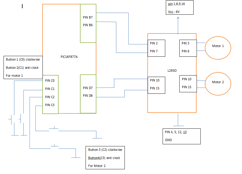
we manage to construct the circuit and do the pic programming..(PIC16F877A)
our problem is that the voltage from pic to the l293d(motor driver) is very low..we getting 1v instead of 3v..
Hope you guyz can help us on how to overcome this problem..

Thanks
 

Definitely something is wrong. You should get at least 5V at the i/o pin of the PIC.
 

Maybe your power source can't manage all circuits.
What is your power source's specs? (voltage and current)
 

Yes I agree with you luciferus. But it depends also to the external load @ o/p on uc, that may be drawing more current. I think sk8ter87 have to check the driver ckt once again(i mean the rating of the driver).
 

Got short circuited somewhere or loose soldering of wires connected to the controller/supply?
Regards,
Jerin.
 

Maybe your power source can't manage all circuits.
What is your power source's specs? (voltage and current)

Yes I agree with you luciferus. But it depends also to the external load @ o/p on uc, that may be drawing more current. I think sk8ter87 have to check the driver ckt once again(i mean the rating of the driver).

Luciferus & Sam ..i manage to control the robot forward and backward at first time..
after that i tried to add function that can control robot to right and left,this the time problem occurred..
the forward and backward working fine,but the left and right got problem..
the motor is working but not like it suppose to work..it working really slow..after measure it,the voltage is around 1v compare to at least 3v
by the way,i'm using 9v as my power source..

Got short circuited somewhere or loose soldering of wires connected to the controller/supply?
Regards,
Jerin.

I check already,everything it's ok..but the power to the motor is still low..
 

the voltage is around 1v compare to at least 3v
by the way,i'm using 9v as my power source...

Where comes 3v? If you are powering with 5v to the pic then the output on the io should be 5v unless you are using pwm
 

what is your motor rating? Its may be more as compare to the supply. I think you have to increase the power....
 
Last edited:

Where comes 3v? If you are powering with 5v to the pic then the output on the io should be 5v unless you are using pwm

Nandhu015..
sorry bro..may be i got wrong info about the 3v..
but our problem,we only able to perform 2 of 4 operation at the time..
the other 2 operation is working,but the motor rotate very slow..
hope you can help me..

---------- Post added at 17:54 ---------- Previous post was at 17:53 ----------

what is your motor rating? Its may be more as compare to the supply. I think you have to increase the power....

hmm..but the power required for the pic only 5v only..
 

what is the battery & motor power rating.

---------- Post added at 18:02 ---------- Previous post was at 17:59 ----------

I am not asking for pic.
 

i guess, you have programming problems with the PWM, If you are using it. Why don't you check the output voltage without connect the driver and check the fly-backs as well
 

I dont think ucsam its of pwm problem because the motor is rotating but it is slow. Hence it may not be getting efficient power from supply. If sk8ter87 can provide the circuit diag it will be more clear.

---------- Post added at 18:54 ---------- Previous post was at 18:12 ----------

Nandhu015..
sorry bro..may be i got wrong info about the 3v..
but our problem,we only able to perform 2 of 4 operation at the time..
the other 2 operation is working,but the motor rotate very slow..
hope you can help me..

---------- Post added at 17:54 ---------- Previous post was at 17:53 ----------


hmm..but the power required for the pic only 5v only..

& 5V is not power
 

I dont think ucsam its of pwm problem because the motor is rotating but it is slow. Hence it may not be getting efficient power from supply. If sk8ter87 can provide the circuit diag it will be more clear.

---------- Post added at 18:54 ---------- Previous post was at 18:12 ----------


& 5V is not power

Yup sam,we not getting efficient power from power supply..The attachment below is how the circuit look like..
 

Yup sam,we not getting efficient power from power supply..The attachment below is how the circuit look like..

Your schematic diagram is wrong you first correct it,study the power driver properly, & then show me the circuit ok.
Your supply is also less make it to 24 W to make your driver run.
 

Yup sam,we not getting efficient power from power supply..The attachment below is how the circuit look like..

You connect pin 10 and pin 15 to the motor as well as the PIC?
 

How much voltage does your motors need?
How many current does your motors need?
How many current can your power source provide?
Why are you using 6v, if you said that you have a 9v source?
 

can you post your PIC16F codes here? There seems to be something wrong with what you are doing. May be your sequence is wrong in driving the H bridge?
 

The driver L293 ,D/E/DNE ,current draw like hell!!!Abaut 50mA in stan-by and 80mA in 1 Ch ,wit 2 ch 100mA!If you without L293 on the pin of the MCU hawe 5 V -then the problem is in power suplay.If not try wit other MCUwithout!!!!! L293 how the pin state is. In my expirianse with l293 i had 2 times pin burnd out on the Atmega8.And L293 is 5V !not 6!!!if you want a use with more then 5 v then the power of the motors /motor suplly is pin 8 from 5 to 30 V depending of motor V.
Try to change l293 and supply her with 5V ,no more !
 

can you post your PIC16F codes here? There seems to be something wrong with what you are doing. May be your sequence is wrong in driving the H bridge?

below is the code:

if there is any error .. plz do help me to correct it since im a newbie in PIC programming
 
Last edited:

Your sequence most probably wrong. You only control one side. By using this you need to control all 4 sides. If you do what you have done, you have shorted part of the power source to GND.

---------- Post added at 15:01 ---------- Previous post was at 15:00 ----------

One sample:

void motor_stop(){
digitalWrite(motor_left[0], LOW);
digitalWrite(motor_left[1], LOW);

digitalWrite(motor_right[0], LOW);
digitalWrite(motor_right[1], LOW);
delay(25);
}

void drive_forward(){
digitalWrite(motor_left[0], HIGH);
digitalWrite(motor_left[1], LOW);

digitalWrite(motor_right[0], HIGH);
digitalWrite(motor_right[1], LOW);
}

void drive_backward(){
digitalWrite(motor_left[0], LOW);
digitalWrite(motor_left[1], HIGH);

digitalWrite(motor_right[0], LOW);
digitalWrite(motor_right[1], HIGH);
}

void turn_left(){
digitalWrite(motor_left[0], LOW);
digitalWrite(motor_left[1], HIGH);

digitalWrite(motor_right[0], HIGH);
digitalWrite(motor_right[1], LOW);
}

void turn_right(){
digitalWrite(motor_left[0], HIGH);
digitalWrite(motor_left[1], LOW);

digitalWrite(motor_right[0], LOW);
digitalWrite(motor_right[1], HIGH);
}
 

Status
Not open for further replies.

Similar threads

Part and Inventory Search

Welcome to EDABoard.com

Sponsor

Back
Top