Continue to Site

Welcome to EDAboard.com

Welcome to our site! EDAboard.com is an international Electronics Discussion Forum focused on EDA software, circuits, schematics, books, theory, papers, asic, pld, 8051, DSP, Network, RF, Analog Design, PCB, Service Manuals... and a whole lot more! To participate you need to register. Registration is free. Click here to register now.

driving motor using joystick and using it's analog to drive in both direction

Status
Not open for further replies.

jerkymotion

Member level 4
Joined
Oct 12, 2010
Messages
73
Helped
28
Reputation
56
Reaction score
28
Trophy points
1,298
Location
NEPAL
Activity points
1,824
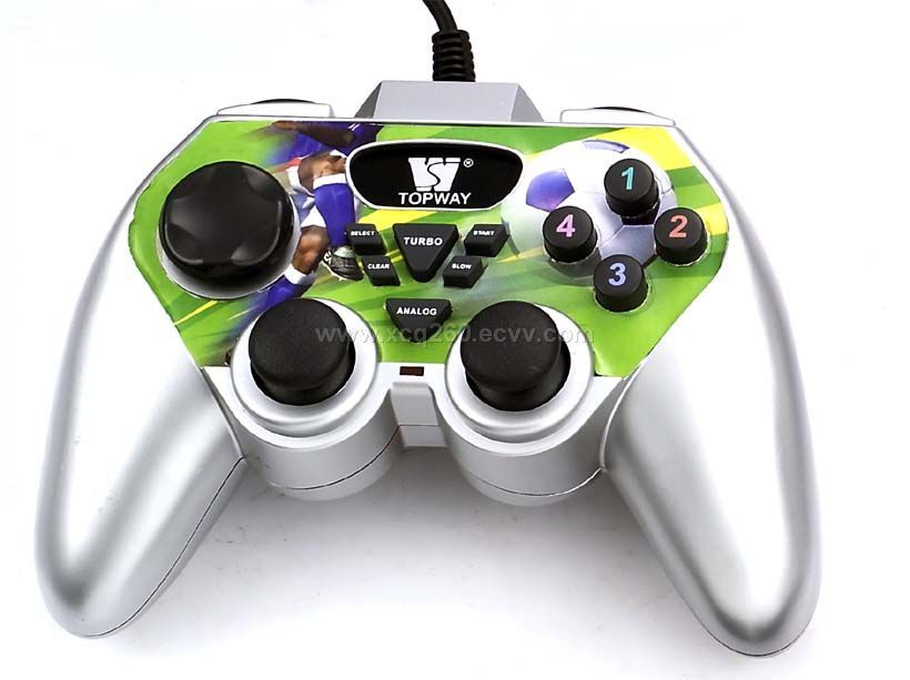
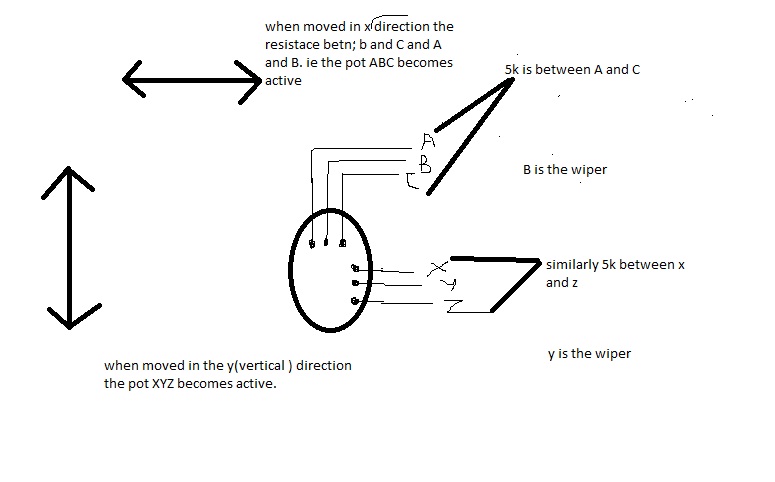
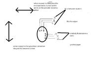
hi all i need to drive a motor using joystick(gamepad) having the analog. I have attached the joypad picture also.. i have posted the internal schematic of the analog part also(internal block structure of joystick's analog)...I have driven motor using joypad's analog in both the direction using microcontroller....but now i need to drive without microcontroller..
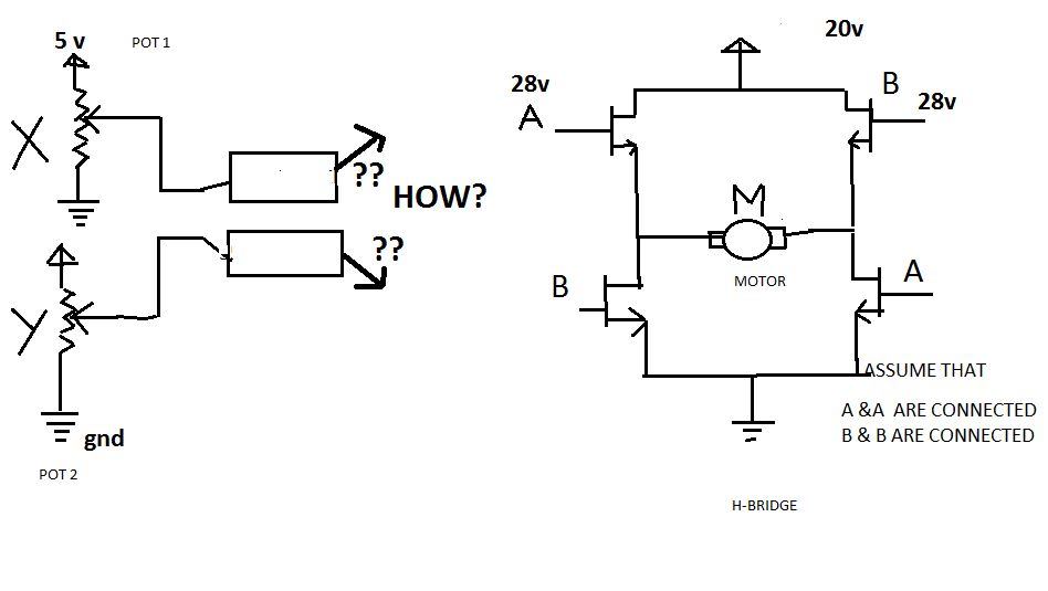
i need to drive motor in one direction when i play the joypad's analog in one direction let us say Y direction.....and in another direction when i play the joypad's analog in another direction let us say X-direction.....
can you please suggest any ideas regarding this....i am waek at circuit design..
 

use H bridge controller and some op amp with smith trigger.. might help =)
 

hi john blue
the analog of joystick i.e. the pot inside it gives linear voltage variation...let us say that when moved in X-direction it gives voltage X and when moved in Y direction gives Y voltage......i tried to use op-amp to drive the gate of Mosfet in H-bridge..but did not work .......the problem is also the when moved in 45degree angle both pot becomes active...Now how to design please help....differential amplifier is what i am thinking but how to design the whole schematics, i have no idea
 
  • Like
Reactions: ssingh

    ssingh

    Points: 2
    Helpful Answer Positive Rating
hi all
all idea will be appreciated please help to drive motor using joystick's analog!!!!

---------- Post added at 11:15 ---------- Previous post was at 11:03 ----------

hi john blue
the problem is not about designing the diiferential amplifier ..
the problem is how to drive that h_bridge part using joystick analog.. ....please help
 
Last edited:
  • Like
Reactions: ssingh

    ssingh

    Points: 2
    Helpful Answer Positive Rating
H bridge need 1 and 0 to drive the NPN and PNP on the adjacent side at one time.
 
hi john
i know all the detail about h-bridge now....
the problem is that i don't have any idea how to drive this h-bridge using joystick's analog...please help
 
  • Like
Reactions: ssingh

    ssingh

    Points: 2
    Helpful Answer Positive Rating
the problem is also the when moved in 45degree angle both pot becomes active...

This is expected behavior of a joystick; it is designed so that a 45 degree angle will activate both pots. The behavior is inherent in the hardware design.
 

yes that behaviour of the analog joystick is what making a head-ache.....
please anyone help me how to drive the H-bridge using analog part of the joystick
suppose i want to rotate the motor in clockwise direction i will move my analog part in X-direction and when to rotate in anti-clockwise direction i will move my analog in Y-direction.......upto this it easy using the voltage from the pot(analog) and using operational to drive the mosfet(h_bridge)...the problem is when i rotate the analog in any direction other than X & Y direction...let us say 45degree...shall i use differential amplifier to to capitalize the two diff voltage coming out of two different pots of analog
how to solve this.....every idea will be appreciated!!!
 
  • Like
Reactions: ssingh

    ssingh

    Points: 2
    Helpful Answer Positive Rating
i used to build robots controlled just like this. from the nether reaches of my memory:

- you had to mix the two signals in an op-amp circuit.
- there are two ways to apply the signal, "locked anti-phase" or "speed magnitude". the first is when 50% duty cycle = 0 average current to the motor and therefore no torque. > 50% means drive forward, < 50% means drive backwards (and use mixing to turn). the speed magnitude means one extra bit is added. the MSB represents direction and the rest of the bits represent magnitude of speed.

have said that, are you sure your joystick actually has a POT inside? i thought all those game pads were fully digital nowadays.

not sure if the above is helpful or not. but as i remember, the trick was to get the mixing correct. maybe google with that key word could help.

Mr.Cool
 

hi Mr cool and jerky motion even i have the same problem as jerkymotion
i have no idea how to use the analog part of my joystick to drive my motor........AS i know i had tried to drive the motor varying the duty cycle from 555timer since you can use pot resistance variance with this ic to vary your duty cycle ....but unfortunetly your frequency also varies...since the DC motors have frequency response characteristics. the response of the motor changes......the two signal coming out of two pot limited me since i did not had idea then...
 

please help me/.................here i have attached the schematics ... i need to drive the motor without using microcontroller and i need to to drive in both the direction using the two pots avialiable in the analog of the joystick......i have no idea what to use so that i can drive my H_bridge...
 

actually jerkymotion, that is looking like a nice plan. very well thought out. that drawing is almost identical to how i started! there are some opamps and a reference to be able to measure the full scale positive and negative. one for each X and Y, just like you have. then you will realize that you must mix the two signals together to get the motor response. so in your block diagram add another single box with both arrows pointing to it and label this box as MIXER. then you have the option on how to develop the output. you can use locked anti-phase (as you are implying in your drawing) or you can have sign-magnitude method. for your drawing, the output of the mixer has 4 outputs, but two of them are the same. A and B (two A's and two B's). if A and B are run simultaneously at 50% duty cycle your average motor speed is zero. for clockwise rotation, then duty_A > duty_B. for counterclockwise then duty_A < duty_B.

in between the mixer output and the H-bridge is another block with the name "gate driver". we can talk about that when you get there.

and please, add anti-parallel diodes to each of your mosfets. the motor would blow up if you tried to run it like that.

keep working on it, you will get there.

Mr.Cool
 
thank's Mr cool
hope your suggestion turns out to be valuable for me..
can u please provide me some information about the mixer..and how to develop the output like.locked anti-phase
 
  • Like
Reactions: ssingh

    ssingh

    Points: 2
    Helpful Answer Positive Rating
Status
Not open for further replies.

Similar threads

Part and Inventory Search

Welcome to EDABoard.com

Sponsor

Back
Top