Continue to Site

Welcome to EDAboard.com

Welcome to our site! EDAboard.com is an international Electronics Discussion Forum focused on EDA software, circuits, schematics, books, theory, papers, asic, pld, 8051, DSP, Network, RF, Analog Design, PCB, Service Manuals... and a whole lot more! To participate you need to register. Registration is free. Click here to register now.

How to detect electric motor slowing down?

Status
Not open for further replies.

jerrypoo

Newbie level 4
Joined
Oct 19, 2010
Messages
5
Helped
0
Reputation
0
Reaction score
0
Trophy points
1,281
Activity points
1,324
Hello all!

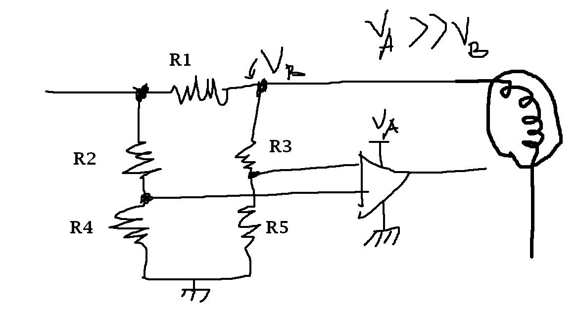
I try to build a simple system that cuts off the power from an electric motor (small, DC motor) when there is too much resistance/work/friction ...

I guss the idea is to put a small resistor and that way measure the electric current. The best would be to use a relay, that would fit some other things, too.

But ... I'm really not good designing anything so all help are welcome! I understand the idea behind this but I need help with the basic design. As simple as possible.

Any idea or design for a simple system?
Thanks in advance, all ideas welcome!
 

That is is a good idea and I'm propably trying that.

However, I'm trying to develop a system where I have several small DC motors running. Each one can be separately stopped by slowing them down enough. The plan is that I get a signal from each when they're on/off.

Something like this ->

2j27yia.jpg


Sorry, I dunno the details :cry:
 

This can be accomplished with in many ways. One: As the motor draws "X" current in normal operation and "Y" when a load is applied, these two can be comapred by a comparator and then a output may be taken to swicth on/off the relay which in turn controls the motor.
OR
The RPM of the motor may be monitored by an Photo transistor-LED setup and a microcontroller monitors the same against a reference RPM set. When that exceeds or deceeds, an output amy be taken to drive the relay in addition the RPM may also be shown on a LCD or seven segment LED display, as a microcontroller is put in to use.
 
This can be accomplished with in many ways. One: As the motor draws "X" current in normal operation and "Y" when a load is applied, these two can be comapred by a comparator and then a output may be taken to swicth on/off the relay which in turn controls the motor. ...

Yeah, that is the idea. But is there any ready (and working) designs around? Even if I undestand this sh*t I'm not good at all to design and build up the prototype :(

(The led or hall sensor is a good idea but unfortunatelly not possible to use in this application.)

Any ideas of how to design this system? All ideas welcome!
 

You can use a OCP circuit using a very small resistor and OP-amp.
 

Yeah, that is my plan (look above) but do you have any idea how to do that? I'm really not good at all with the details :(
Have anyone seen ready made plans?
 

Yeah, that is the idea. But is there any ready (and working) designs around? Even if I undestand this sh*t I'm not good at all to design and build up the prototype. Any ideas of how to design this system? All ideas welcome!

As i understood that you are not good in design and fabrication, please clarify wether you expect any professional guidance from any well qualified designer to build and devlop your project in return for a fee or you expect some one to do the complete project, and give you the complete technology?
 

As i understood that you are not good in design and fabrication, please clarify ...


Sorry, my articulation is not good :)

I have done a whole lot of all kind of small - and simple - electronics. What I'm really unconfortable is this analogic, transistor and op-amp stuff... In theory I could maybe get something to work but to be honest, in this real world, I think I save one or two years if some smart one could help... Look at the drawing above, that's my start :-O ...

I am sure someone, somewhere, have designed a working unit already? Any ideas?
 

you can use optical encoder which is a sensor that measures position or velocity of a shaft. a encoder is a disk that has numerous holes a infrared led is placed at one side of the disk and infrared phototransistor is placed directly opposite to the led. now when the shaft rotates the hole passes the light and output of the phototransisiistor changes continiously produsing a pulse train.the rate at which the pulse is produced corresponds to the rate at which the shaft turns..
now when there is too much of friction the rpm of the motor changes(slows) and you use microcontroller r......but you must set reference rpm so that whenever the rpm deceeds the reference rpm....i.e. slowers down....then you can drive the output signal from the microcontroller which shall drive the transistor which in turn drives the relay to stop the motor...
good luck

---------- Post added at 01:36 ---------- Previous post was at 01:33 ----------

to design it in a analog way::follow the steps mentioned by pranam earlier
 

Hi, you can use this schematic as reference...

important things to consider:

how much is the fault current?
are you critical wit effeciency?
what kinds of equipments for testing can you use? oscilloscope?
 

Attachments

  • eda1.bmp
    2.1 MB · Views: 93

hi anun can u explain your schematics please.....as i see comparator ...but did not found what the comparator is comparing...???
 

hi anun can u explain your schematics please.....as i see comparator ...but did not found what the comparator is comparing...???


Hi jerkymotion, R1 is connected in series with your motor. This acts as your Rsence. This will be a very small resistor with value and wattage computed using your expected fault current.

When a fault is present, the voltage drop accros R1 will increse, thus it will bias the resistors on the input of the comparator. Compute for the values of R2,R3,R4 and R5 with respect to your actual Voltage drop with R1. the input voltage should be stable so to prevent any miss-trigger. use the output of the comparator to controll the input. you can use a fet or a relay for this purpose. also the Vcc of the comparator should always be greater that your input voltage for the motor.
 
Status
Not open for further replies.

Similar threads

Part and Inventory Search

Welcome to EDABoard.com

Sponsor

Back
Top