piggymin
Newbie level 1
HI,
I need help urgently on the Avago optocoupler gate drive.
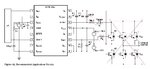
Follow the datasheet recommended application circuit, Vcc2 = 15V and Vee = -5V. I want the Vge (Vout) have a pulse of 15V to -5V which frequency and duty cycle follow the Vin+ (using non inverting).
Now the problem is the Vout frequency will change according to Vin+ frequency but not the duty cycle. The high side duty cycle will always remain at a certain value. The Vout not suppose follow the signal input at Vin+?
Is there anything to do with the DESAT pin? Currently I did not connect any IGBT and DESAT (100ohm and Ddesat diobe) in my testing circuit.
Thanks.
I need help urgently on the Avago optocoupler gate drive.
Follow the datasheet recommended application circuit, Vcc2 = 15V and Vee = -5V. I want the Vge (Vout) have a pulse of 15V to -5V which frequency and duty cycle follow the Vin+ (using non inverting).
Now the problem is the Vout frequency will change according to Vin+ frequency but not the duty cycle. The high side duty cycle will always remain at a certain value. The Vout not suppose follow the signal input at Vin+?
Is there anything to do with the DESAT pin? Currently I did not connect any IGBT and DESAT (100ohm and Ddesat diobe) in my testing circuit.
Thanks.