Continue to Site

Welcome to EDAboard.com

Welcome to our site! EDAboard.com is an international Electronics Discussion Forum focused on EDA software, circuits, schematics, books, theory, papers, asic, pld, 8051, DSP, Network, RF, Analog Design, PCB, Service Manuals... and a whole lot more! To participate you need to register. Registration is free. Click here to register now.

Loop gain and Step response of capacitive feedback fully differential OTA

Status
Not open for further replies.

niranjan1984

Newbie level 6
Joined
Mar 13, 2008
Messages
13
Helped
0
Reputation
0
Reaction score
0
Trophy points
1,281
Activity points
1,388
Hi
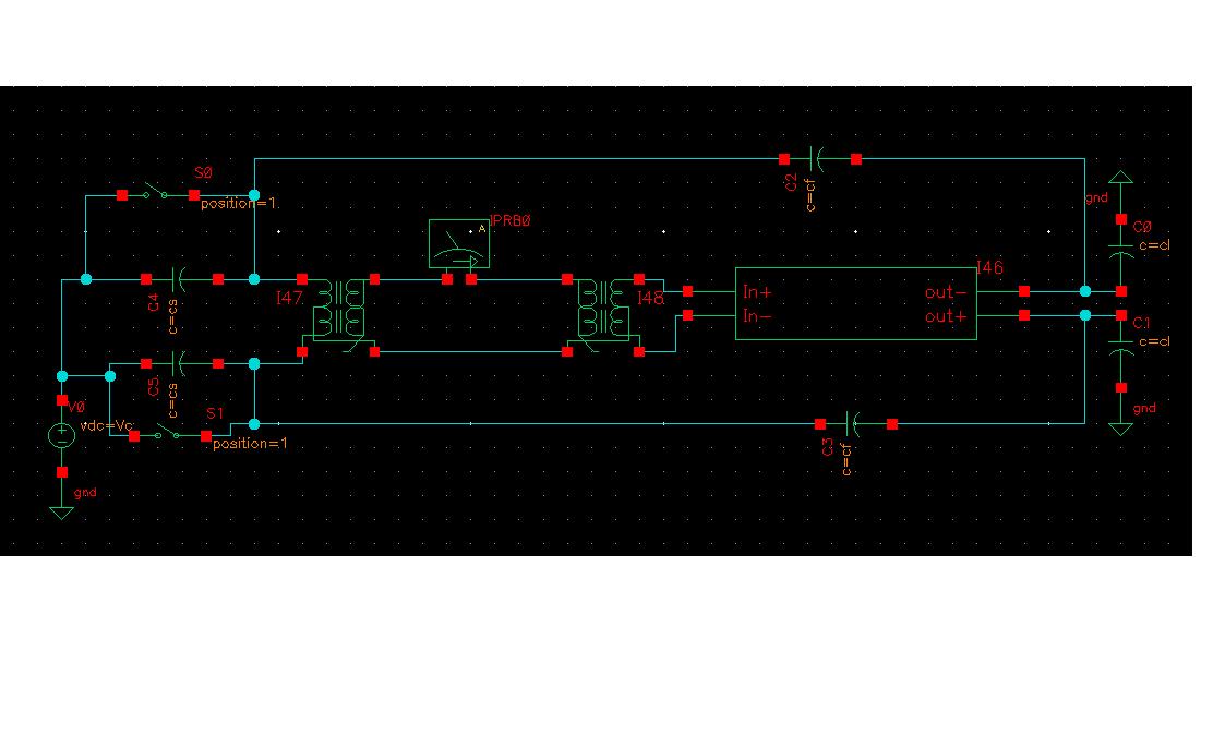
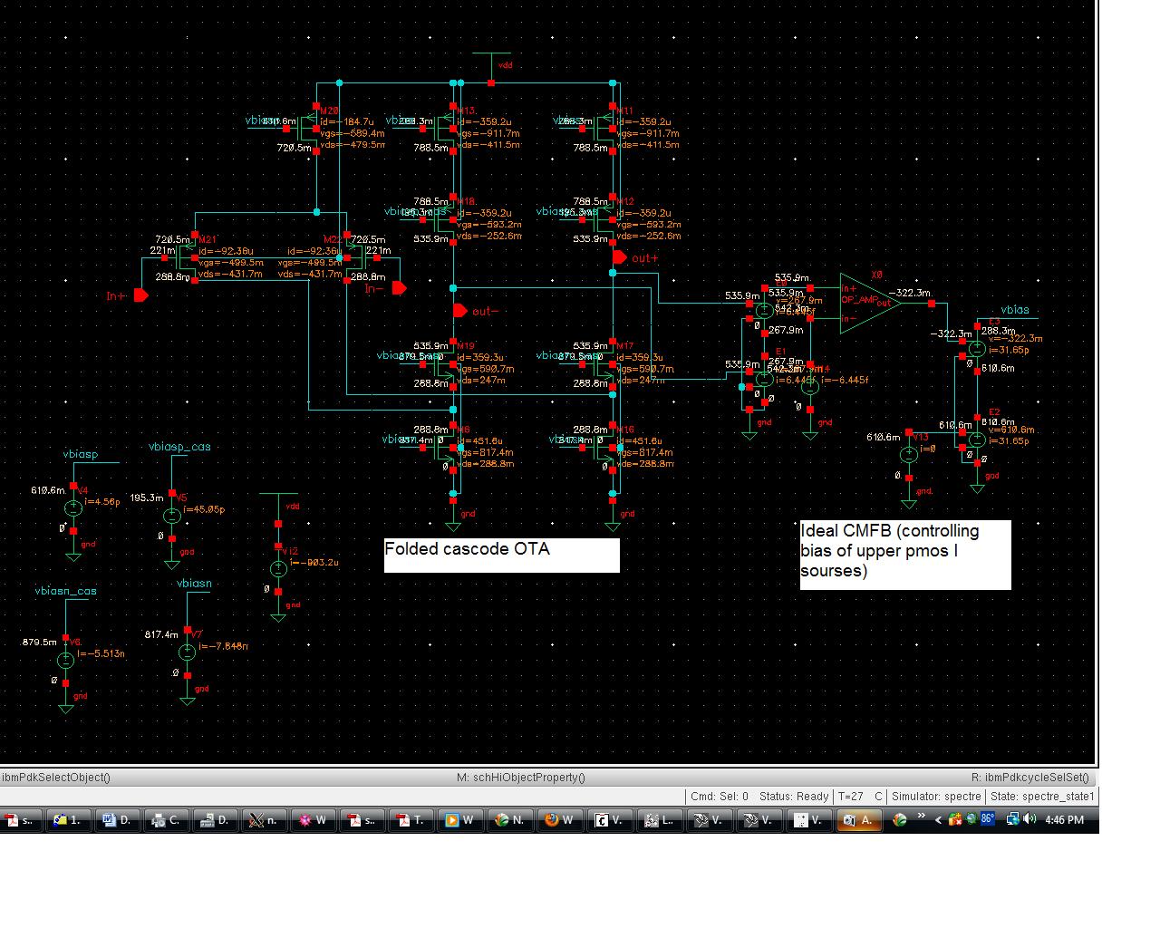
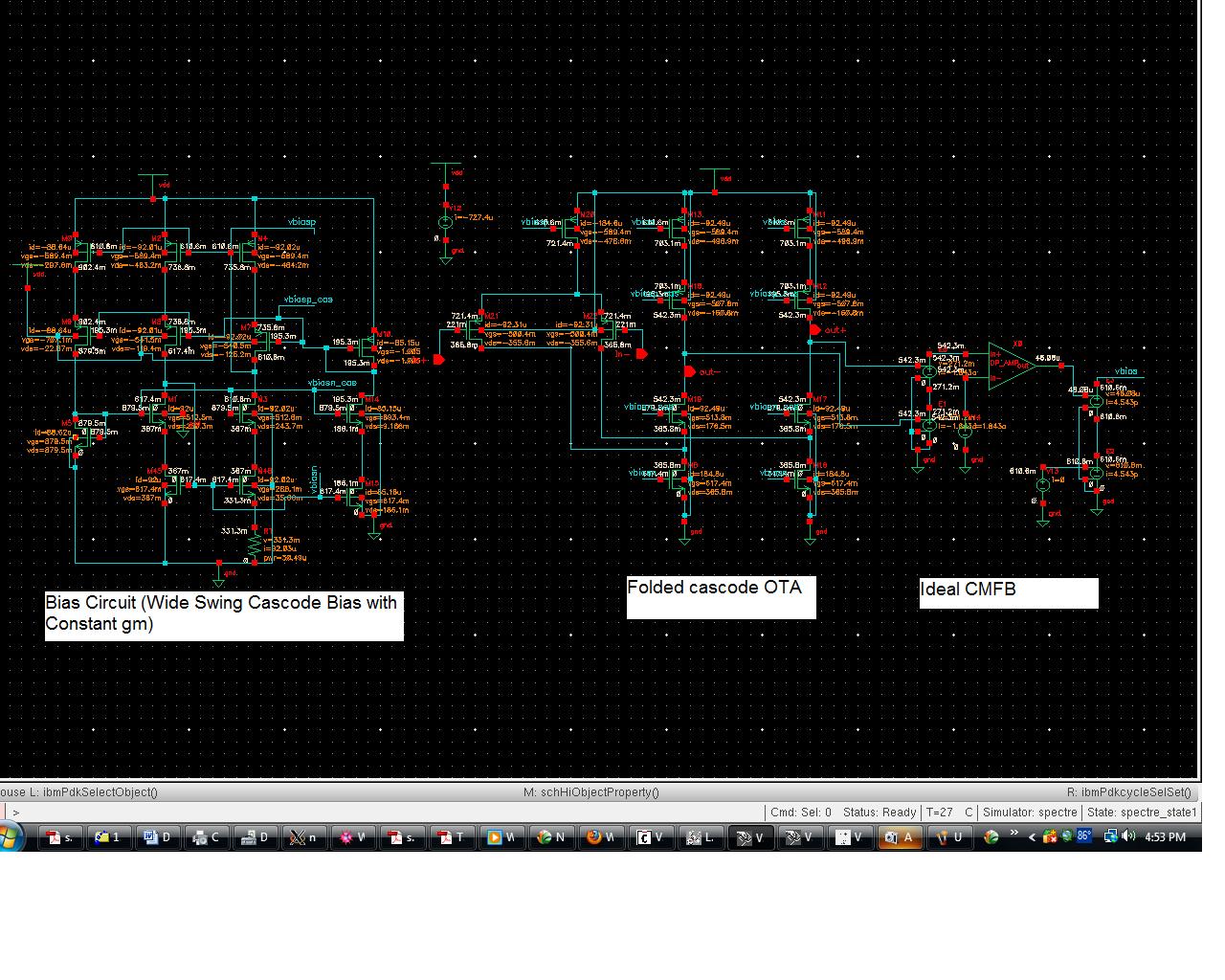
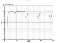
I have designed capacitive feedback fully differentail OTA. I am trying to simulate loop gain and step response of OTA. Fig1 shows the test bench used
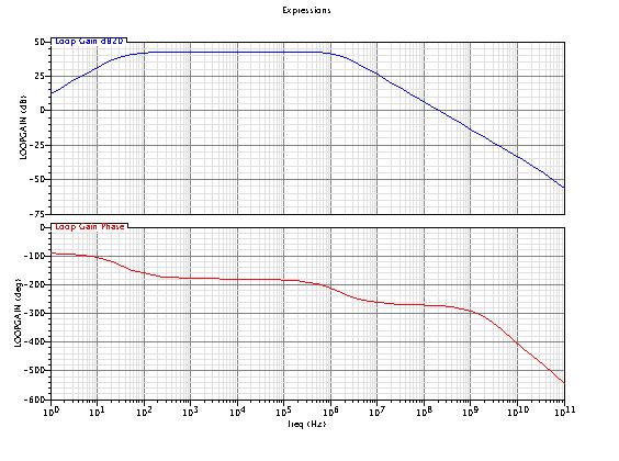
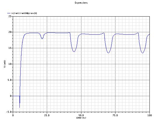
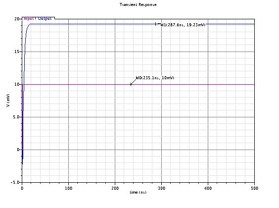
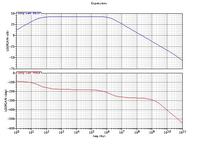
Fig2 shows the loop gain and fig3 shows the step response. I have following questions

1. Why loop gain curve is not flat at the beginning? Theory shows that at low frequency loop gain equals to T0=β.Gm.Ro and hence should be flat

2. Why is the step response showing these humps? Is this because of loop gain issue? or something else

I am not getting this please help.

Thanks


1. Why loop gain curve is not flat at the beginning? Theory shows that at low frequency loop gain equals to T0=β.Gm.Ro and hence should be flat

Although your measurement/simulation concept for the loop gain is not clear to me, I guess the transformer is responsible for the first (rising) part of the magnitude response.

2. Why is the step response showing these humps? Is this because of loop gain issue? or something else

I have no explanation; something must be wrong

(By the way: Your simulation arrangement is not easy to interpret; which loop gain simulation principle are you going to use?)
 

HI
Thanks for the reply. I am using Ideal Balun from analoglib.
 

I believe your CS capacitors are responsible for the high-pass behavior of your circuit. The transient simulation is a mystery...
 
Hi JoannesPaulus
Thanks for the reply. Thats true if I make CS bigger high pass response goes away. But thats not the value designed. So is this high pass response is normal is capacitive feedback circuits? does this affect stability?
 

This response is normal whenever you have a capacitor in series with your signal (intuitively, it blocks DC). The stability should not be affected (in this particular test bench).
 
HI LvW
Thanks for the reply. I am using ideal balun in the simulation. For loop gain siumlation I using .stb analysis in cadence.

---------- Post added at 16:47 ---------- Previous post was at 16:46 ----------

Thanks JoannesPaulus
do you have any idea whats wrong with the step response? This would help.
 

@niranjan1984

The first look at your circuit for the bode plot tells me that at low frequencies you are having a zero kicking in- (differentiator kind of response). The reason i strongly suspect is the presence of capacitive feedback at the negative end of your amplifier.

If possible try to calculate roughly the overall transfer function of your system and calculate the dominant poles and zeros. You can also find out the exact pole zero values from the ADEXL spectre simulator.

From the magnitude plot : gain is ~10dB and then increases to 50dB (the initial response is because of the zero and then the dominant pole kicks in). Similarly your phase does not start from zero, but -90 instead!

WRT the step response my guess is its wrt to the switches S0 and S1. Try checking the timing again!

Hope this helps.
 

Thanks for your reply guys. I am trying to find whats wrong with step response. So I am attaching schematic of OTA with this post (fig 1) . I am using

1. Floded cascode OTA
2.With Wide swing constant gm bias (described in Analog Integrated circuit design by David Johns & Ken Martin pg 259)
3.and Ideal CMFB

This circuit gives the step response attached before. Then I removed my bias circuit and used ideal voltage sources to bias (fig 2) still used the same CMFB. The step response of this circuit is attached in (fig 3). It looks like the ringing problem is gone.

1. I am getting ringing problem because of bias circuit? should I check its stability ? and how to check?
2. Is ideal CMFB giving me the problem?

Please help me to solve this problem

Thanks


Status
Not open for further replies.

Part and Inventory Search

Welcome to EDABoard.com

Sponsor

Back
Top