shibendu.mahata
Newbie level 3
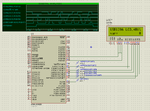
Hi friends, I am trying to send a string "GREAT" to the JHD162A LCD operating in 4-bit mode, interfaced with pic18f4220 uC through PORTB<7:4>.PORTB<2> and PORTB<3> are the RS and E resp. and RW is permanently grounded.However, the LCD doesn't display anything except 16 squares in the first line. I have used MPLAB for the coding, with the uC operated at 4MHz. I have tried sending single character as well but to no avail.Can you kindly tell me where the initialization of the LCD is wrong.
;RB2=RS,RB3=E
#INCLUDE<P18f4220.INC>
CONFIG OSC=XT
CONFIG WDT=OFF
CONFIG BOR=OFF
CONFIG CCP2MX=ON
CONFIG PBAD=DIG
CONFIG FSCM=OFF
CONFIG IESO=OFF
TEMP EQU 0X00
TEMP1 EQU 0X01
ORG 0
BRA MAIN
MAIN:ORG 0X20
AGAIN:CALL DELAY
MOVLW 0X0F
MOVWF ADCON1
CLRF TRISB
CLRF TRISC
CLRF TRISD
CLRF PORTB
CLRF PORTC
SETF PORTD
BCF PORTB,3
MOVLW 0X30
MOVWF TEMP
MOVWF TEMP1
CALL DELAY
CALL CMDWT
MOVLW 0X30
MOVWF TEMP
MOVWF TEMP1
CALL DELAY
CALL CMDWT
MOVLW 0X30
MOVWF TEMP
MOVWF TEMP1
CALL DELAY
CALL CMDWT
MOVLW 0X20
MOVWF TEMP
MOVWF TEMP1
CALL DELAY
CALL CMDWT
MOVLW 0X28
MOVWF TEMP
MOVWF TEMP1
CALL DELAY
CALL CMDWT
MOVLW 0X28
MOVWF TEMP
MOVWF TEMP1
CALL DELAY
CALL CMDWT
MOVLW 0X28
MOVWF TEMP
MOVWF TEMP1
CALL DELAY
CALL CMDWT
MOVLW 0X0E
MOVWF TEMP
MOVWF TEMP1
CALL DELAY
CALL CMDWT
MOVLW 0X01
MOVWF TEMP
MOVWF TEMP1
CALL DELAY
CALL CMDWT
MOVLW 0X06
MOVWF TEMP
MOVWF TEMP1
CALL DELAY
CALL CMDWT
MOVLW 0X84
MOVWF TEMP
MOVWF TEMP1
CALL DELAY
CALL CMDWT
MOVLW A'G'
MOVWF TEMP
MOVWF TEMP1
CALL DELAY
CALL DATWT
MOVLW A'R'
MOVWF TEMP
MOVWF TEMP1
CALL DELAY
CALL DATWT
MOVLW A'E'
MOVWF TEMP
MOVWF TEMP1
CALL DELAY
CALL DATWT
MOVLW A'A'
MOVWF TEMP
MOVWF TEMP1
CALL DELAY
CALL DATWT
MOVLW A'T'
MOVWF TEMP
MOVWF TEMP1
CALL DELAY
CALL DATWT
GOTO AGAIN
CMDWT:MOVFF TEMP1,WREG
ANDLW 0X0F0
MOVWF PORTB
BCF PORTB,2
BSF PORTB,3
CALL DELAY
BCF PORTB,3
MOVFF TEMP,WREG
ANDLW 0X0F
MOVWF TEMP
RLNCF TEMP
RLNCF TEMP
RLNCF TEMP
RLNCF TEMP
CALL DELAY
MOVFF TEMP,PORTB
BCF PORTB,2
BSF PORTB,3
CALL DELAY
BCF PORTB,3
RETURN
DATWT:MOVF TEMP1,W
ANDLW 0X0F0
MOVWF PORTB
BSF PORTB,2;;;;;;;;;
BSF PORTB,3
CALL DELAY
BCF PORTB,3
MOVFF TEMP,WREG
ANDLW 0X0F
MOVWF TEMP
RLNCF TEMP
RLNCF TEMP
RLNCF TEMP
RLNCF TEMP
CALL DELAY
MOVFF TEMP,PORTB
BSF PORTB,2;;;;;;;;;;;;;;;
BSF PORTB,3
CALL DELAY
BCF PORTB,3
RETURN
DELAY:BCF INTCON,TMR0IF
MOVLW 0X00
MOVWF TMR0H
MOVWF TMR0L
MOVLW B'10010111'
MOVWF T0CON
LOOP:BTFSS INTCON,TMR0IF
BRA LOOP
BCF INTCON,TMR0IF
RETURN
;GOTO AGAIN
END

")