Continue to Site

Welcome to EDAboard.com

Welcome to our site! EDAboard.com is an international Electronics Discussion Forum focused on EDA software, circuits, schematics, books, theory, papers, asic, pld, 8051, DSP, Network, RF, Analog Design, PCB, Service Manuals... and a whole lot more! To participate you need to register. Registration is free. Click here to register now.

Ethernet Interface - Center Tapped Transformer

Status
Not open for further replies.

newbie101

Member level 2
Joined
Apr 25, 2005
Messages
47
Helped
7
Reputation
14
Reaction score
3
Trophy points
1,288
Activity points
1,751
Hi All,

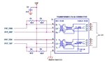
Attached is an example of a recommended interface circuit for Ethernet integrated into a Microcontroller.

a) May I know the purpose of the center tap in the transformer? Since TXP & TXN are diff pairs, wouldn't a non center tapped transformer be sufficient?

b) Is it ok to put the choke on the uC side of the transformer?
uC <--> choke <--> transformer <--> RJ-45

c) Please explain the 75ohm termination on the secondary side.

Thanks,
Newbie101
 

Attachments

  • Ethernet.JPG
    Ethernet.JPG
    34.9 KB · Views: 315

a. The center tap is required to supply the DC bias current with some PHY chips. It also further reduces coupled common mode interferences. In any case, you should follow the PHY datasheet.
b. Not in the present circuit. Generally, if the center tap bypasses the choke, the transformer obviously must not be reversed.
c. The 75 ohm termination is intended for attenuation of common mode waves.
 
Hi All,

May I know where should I put the: -
a) Transmit Termination Resistors
b) Receive Termination Resistor

Nearer to PHY or to Transformer?

Thanks,
Newbie 101
 

The basic idea is to have a both sided terminated 100 ohm differential transmission line between both PHYs. Thus the termination resistors have to be placed near the PHY, the PCB traces between magnetics and PHY should be designed for 100 ohm differential impedance.
 
Thanks FvM.

However, isn't termination supposed to be placed at end of the line? (i.e. end of signal path)
Thus for TxN & TxP the termination resistors are placed near the transformer??
 

Thus for TxN & TxP the termination resistors are placed near the transformer??
No, the matched impedance signal path is PHY to PHY.
 
Status
Not open for further replies.

Similar threads

Part and Inventory Search

Welcome to EDABoard.com

Sponsor

Back
Top