Continue to Site

Welcome to EDAboard.com

Welcome to our site! EDAboard.com is an international Electronics Discussion Forum focused on EDA software, circuits, schematics, books, theory, papers, asic, pld, 8051, DSP, Network, RF, Analog Design, PCB, Service Manuals... and a whole lot more! To participate you need to register. Registration is free. Click here to register now.

IR2110 test for driving mosfet

Status
Not open for further replies.

etiquoe

Member level 1
Joined
Feb 18, 2010
Messages
35
Helped
4
Reputation
8
Reaction score
1
Trophy points
1,288
Location
Indonesia
Activity points
1,525
hi,
i'm gonna use ir2110 for driving my bldc h-bridge.
so for testing, i connected it with mosfet like this:


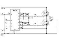
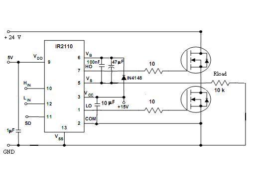
i fed the Lin pin with 60Hz noninverting PWM signal, and 60Hz inverting PWM signal for Hin pin.

for bootstrap capacitor, i use 0.1uF ceramic and 47uF electrolytic in parallel.

but both of the mosfets got pretty warm in few seconds, and then damaged.

need help :|

anyone?
 

The schematic looks O.K., except for using 1N4148 as bootstrap diode, that may be possibly damaged by the 47 uF inrush current. I assume, that the missing connection between load and FET output is only a drawing fault.

If 1N4148 stands the current, there's probably a problem with the input waveform, or the real circuit is different from the schematic.
 
  • Like
Reactions: pejicmato

    V

    Points: 2
    Helpful Answer Positive Rating

    pejicmato

    Points: 2
    Helpful Answer Positive Rating
so, what is apropriate diode for my circuit?

the real circuit is same with the schematic, and the input wave form as i mentioned above.

how about dead time?
is it not also the problem?
 

    V

    Points: 2
    Helpful Answer Positive Rating
For 60 Hz, 1N4001 would be o.k. Deadtime may be a problem. If the input signals are exactly inverted (not overlapping), the IR2110 unsymmetric switching time would be sufficient to avoid cross-conduction. Particularly at 60 Hz, the additional losses should be acceptable. But I agree, that you may want to provide additional deadtime. If the circuit layout isn't that good, cross conduction current spikes may cause a lot of problems.
 

    etiquoe

    Points: 2
    Helpful Answer Positive Rating
    V

    Points: 2
    Helpful Answer Positive Rating
FvM said:
For 60 Hz, 1N4001 would be o.k

how about using frequency up to 20 kHz?
 

    V

    Points: 2
    Helpful Answer Positive Rating
Then you should us a fast diode with sufficient current rating.
 

    V

    Points: 2
    Helpful Answer Positive Rating

    etiquoe

    Points: 2
    Helpful Answer Positive Rating
thanks,
i increased the gate resistor value and connected a diode parallel to the gate resistor as an-978 mentions to provide additional dead time. it worked :D
 

    V

    Points: 2
    Helpful Answer Positive Rating
hi FvM
can i connect the VDD pin to 5v logic voltage?? and can i connect the Hin and Lin directly to the PWM pins in my AVR microcntroller??
thank you in advance
 

    V

    Points: 2
    Helpful Answer Positive Rating
can i connect the VDD pin to 5v logic voltage?? and can i connect the Hin and Lin directly to the PWM pins in my AVR microcntroller??
IR2110 is working good with 5V VDD, at lower voltages (e.g. 3.3V), delay times are increasing. HIN and LIN can be driven from an uC or a programmable logic circuit with CMOS logic level.
 
  • Like
Reactions: Hassan_zytoon

    V

    Points: 2
    Helpful Answer Positive Rating

    Hassan_zytoon

    Points: 2
    Helpful Answer Positive Rating
thank you FvM
i try to build my own circuit and it work well

I want to turn on the high side MOSFET for a long time , but it turns off due to the discharging of the bootstrap capacitor
i want to know about the charge pump technique .
can you help me??

thank you in advance
 

I think there's no universal solution for 100% high side driver duty cycle. It depends on voltage levels, speed, available supply voltages. Some IRF application notes are adressing the topic, but i didn't yet made a circuit like this.
 

    V

    Points: 2
    Helpful Answer Positive Rating
thank you FvM

can you explain what is the dead time??

thank you in advance
 

    V

    Points: 2
    Helpful Answer Positive Rating
hi all ...
how to calculate time periode needed for charging the bootstrap capacitor, to ensure that the bootstrap capacitor fully charged?

thanks
 

What MOSFETs you are using.
 

what is the dead time??


when you turn the high side on and the low side off, and then you want to change the condition become the reverse (turn the high side off and the low side on), you'll need deadtime between the two condition by turning off both high side and low side FET, to avoid 'shoot through'
 

Hi etiquoe, I suggest you download the application note of the ir2110 it's explain the problem you are facing as well.
 

BA159 (fast switching diode) will be the better choice just go for googling..chears
 

Status
Not open for further replies.

Part and Inventory Search

Welcome to EDABoard.com

Sponsor

Back
Top