Continue to Site

Welcome to EDAboard.com

Welcome to our site! EDAboard.com is an international Electronics Discussion Forum focused on EDA software, circuits, schematics, books, theory, papers, asic, pld, 8051, DSP, Network, RF, Analog Design, PCB, Service Manuals... and a whole lot more! To participate you need to register. Registration is free. Click here to register now.

Regulator is overheating ....

Status
Not open for further replies.

sherazi

Banned
Joined
Feb 15, 2010
Messages
388
Helped
61
Reputation
126
Reaction score
61
Trophy points
1,318
Location
Muscat, Oman, Oman
Activity points
0
Good Day to all,

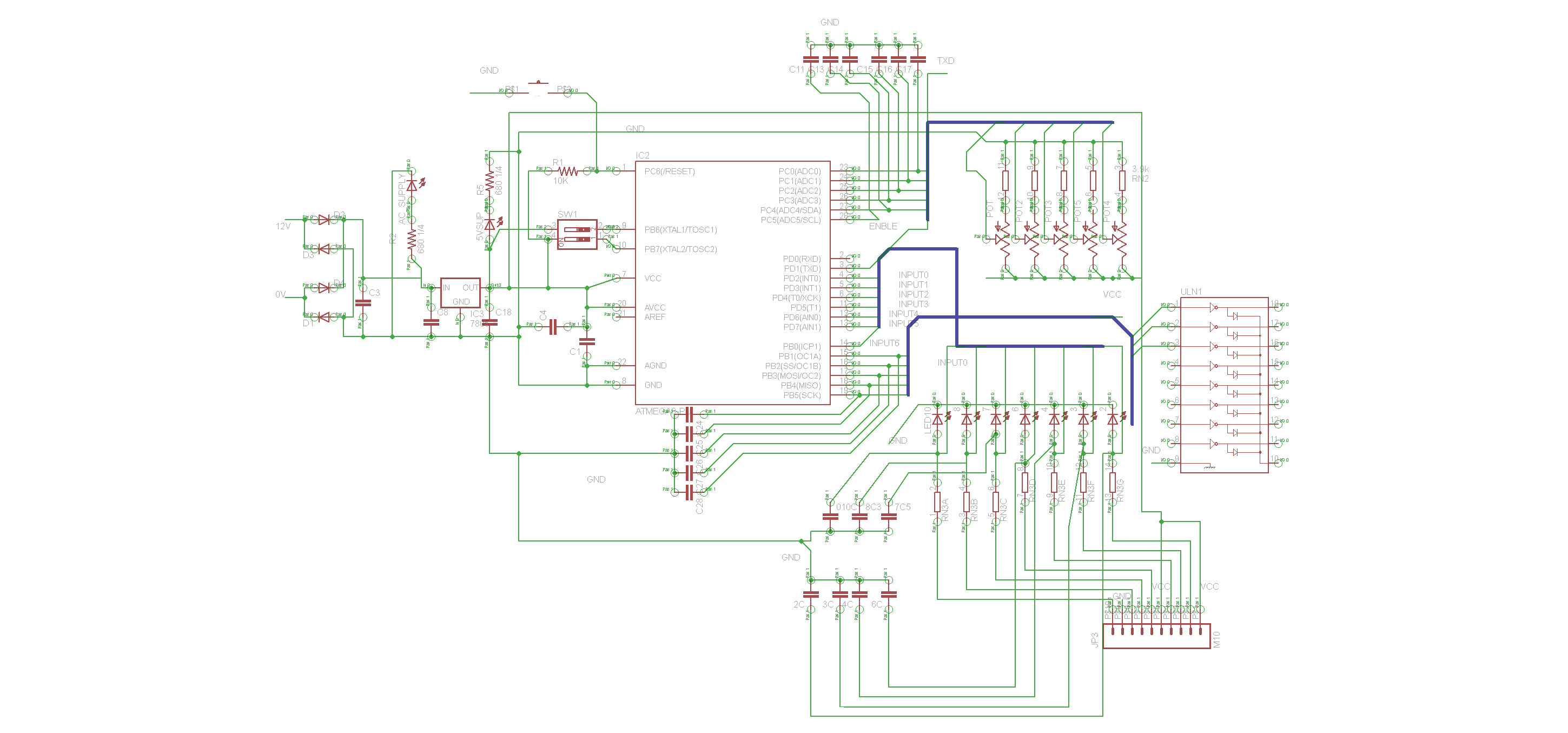
i designed this circuit , and the problem i am having with this is the regulator gets heated too much, i tried to configure out any reason but failed...

I am attaching the schematic (sorry if its messy) so that you may point out any reason for that,

i should mention that the regulator is 7805 and it gets heated in 10 secs to an extend that i cant keep the finger over it for more than 3 secs....


Hi,
For 7805 Input voltage should be from 7 to 9 V. In your case you use 12 V Input voltage which is a lot.
 

hello,

as always, you have too much power to evacuate with a 78xx regulator ...
take a look at a smps regulator like lm2575, almost the same schematic, with a diode and an inductor more and quite no heating anymore ...

you have too much power to dissipate from 12v to 5v. if your circuit consumes let's say 100mA, that makes (12-5)*0.1 = 0.7W to dissipate which is too much without an heatsink ... and it wastes energy ...

regards.
 

7805 can accept Vin up to 35V for output curent up to 1A, BUT(!!!!) you must calculate the Power Loss (heat).

Heating on 7805 is:

P = (Vin-Vout)*I = (Vin-5)*I

TO220 package has a thermal Coefficient 65 C/W.

For example, for Vin=12 and I=0,3 A (these values are far away from upper limits), power loss is calculated: (12-5)*0,3 = 2,1 W
If you use the 7805 alone, without heatsink, the temperature on chip is calculated:
Tchip = 2,1*65+Tenv = 136 C + Tenv (Tenv is the ambient temperature.
With this configuration you have to use an extra heat sink.
I think that now you can make the calculations for your case.
 

but i also have seen the same sort of boards that use 7805 and its not that much hot, iwould change it if thats the problem but as far as i think there is some oher problem... i just used the same 12v input for another circuit of avr it was a light bell for someone who couldnt hear, there was an input push button ,and a relay to switch lights (blink them)... and had a 7805 @ input... i did use 12v there and it was all fine

Added after 2 minutes:

that values....i didnt even thought of 65C/W...
but i wonder why some boards that have same load elemnets and same 12v supply can be so much cool than this.....
 

Power Loss counts, not only Vin!
If you have a circuit that needs 50mA you can use Vin=18 V without heating problems.
 

how much current would an avr atmega328p take?

Added after 4 minutes:

i am asking that because when i remove the mcu its quite although the relays and moc and pots and the input switches all are still there
 

Measure current on your board. ATmega328 normaly requires some mA without outputs.
Put another atmega328 and measure again.
Something is wrong.....
 

idont know whats the problem every atmega328 even atmega168 and atmega8 does that heating... if its removed then there is no heating... and thats the reason i asked to point out any mistake in the circuit that has been attached
 

Hi,
Is your GND-pin at AT Mega connected to the systems GND?
Measure pls. for resistance from the top of processor pin(on th package) to i.e. supply GND...
Seems you have a back supplying or some shorted capacitor on the uP!
K.
 

i just removed the avr and found that now the uln gets heated alot, specially over the com and gnd pin...area... if i remove the com pin connction from 12V of the supply the heating stops... right now regulator doesnt get hot... even avr being placed....

Added after 33 seconds:

Both Gnds are connected its a short...

Added after 26 seconds:

i mean that both GNDs are short
 

Have you made a PCB from the circuit? If so, run the ERC on the schematic and DRC on the PCB.

Keith.
 

sherazi said:
...now the uln gets heated alot, specially over the com and gnd pin...area... if i remove the com pin connction from 12V of the supply the heating stops... right now regulator doesnt get hot... even avr being placed....
Aha, what abot hes outputs & pin 10?
What for a resistance can you measure between all individual outs/pin 10 and GND (& Vcc too) pls?
Maybe ULNs pin10 has a GND short_can you change it too... Btw;is pin 10 open?
K.
 

i disconnected uln pins GND and COMMON and now the regulator doesnt get heated...

but still the uln gets heated ...though not as much as it gets when the common is connected but still... is it faulty uln or circuit?

Added after 2 minutes:

common is 12v that drives the uln and is same here and at the V-REG input
 

amazingly

the resistances are as follows

b/w pin 9-10..........0.816K
b/w pin 8-11..........17K
b/w all other inputs and their corresponding output shows some what 6.8M

that means i should change it with another one... i will do it then tommmorrow

Added after 59 seconds:

its ULN2804,

Added after 28 seconds:

keith1200rs said:
What is the part number of the ULN chip?

Keith.
its ULN2804
 

sherazi said:
...but still the uln gets heated ...though not as much as it gets when the common is connected but still... is it faulty uln or circuit? ...
Yea, thesm is faulty in function,
or check very good the PCB at pin 9 & 10, it can have a short too...
You can measure it with a simple ohm meter_pull th eIC, have you some resistancese measured between "in air" pins & to GND -search for that subject/origin, but measure the IC self too, can be that the PCB is OK but ULN has a short.
K.
 

OMG! ........ i just made 12V ac net labeled as 12V and when i had to connect 12 VDC to COM pin of ULN and RELAYS, i again named it 12v instead of connecting it directly which was 12V AC....

This means the coil of relays gets one signal through micro-controller, and a AC12V from the Transformer... further more ULN also gets 12V AC there...... Is this the source of heating?
 

Clear:
in the "negative periode" you will have an opened diode on Common to GND/through parasite diodes_parallel with the output transistors :-(...
BTW; has your ULN pin10_9 in both directions ca. 800 Ohm?_than is in short/defect....
Anyway; why didnt you connected Pin10 to the DC12V/Regulator input!? I think your relays are on that potential too.
K.
 

    sherazi

    Points: 2
    Helpful Answer Positive Rating
Status
Not open for further replies.

Similar threads

Part and Inventory Search

Welcome to EDABoard.com

Sponsor

Back
Top