Continue to Site

Welcome to EDAboard.com

Welcome to our site! EDAboard.com is an international Electronics Discussion Forum focused on EDA software, circuits, schematics, books, theory, papers, asic, pld, 8051, DSP, Network, RF, Analog Design, PCB, Service Manuals... and a whole lot more! To participate you need to register. Registration is free. Click here to register now.

6 Layer Stackup & Drill Pairs

Status
Not open for further replies.
bert_kak said:
Guys any idea on how much line width will I use for a 75ohms composite video signal? Thanks

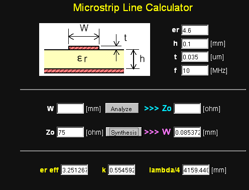
It depends on the board thickness and number of layers. Try an impedance calculator. Download Appcad or use something like this:

https://www.technick.net/public/code/cp_dpage.php?aiocp_dp=util_pcb_imp_calculator

tennythomas said:
The Simple PCB Impedance Calculator, PCB Stackup Impedance Calculator and
Trace Current Calculator are available in this link - **broken link removed**.

Requires registration.

Keith.
 

Im using SB200 from Polar but what I get is very small line width compared to the evaluation boards we have here. All of the digital signals we're matched based on the SB200 but the 75ohm analog signal was different. It was always 0.25mm above in line width in all the evaluation boards that I saw but the SB200 outputs way less than those. Are there special consideration in analog signal? thanks
 

Analog/digital - it is all the same. What are the PCB parameters you are using (board thickness, dielectric etc)?

Keith.
 

keith1200rs said:
Analog/digital - it is all the same. What are the PCB parameters you are using (board thickness, dielectric etc)?

Keith.

here is my stack up.
middle core will be 1.24mm so it will be 1.6mm
on the right side is the computed line width for 50ohms single impedance line.
but when i try to compute for 75ohms it produces error because the line width would be too small.
 

That diagram is for a 50 ohm trace on 0.1mm thick PCB. For standard 1.6mm PCB I would expect the inner core to be thicker than 1.24mm.

Anyway, at 1.24mm you would need around 1mm wide track for 75 ohms and for 1.4mm around 1.15. How does that compare to your calculations?

By the way, bear in mind for video the bandwidth is relatively low. For short track lengths the impedance won't be critical. For example a 10mm track at 10MHz is only 0.2 degrees electrical length.

Keith.
 

Hi Bert,
I used another older SW over long years from Polar, but their isnt usable on Internet PCs in the past ca. 8 years :-(...
It has had never bad values, seems to be very similar as your version...
For PRACTICABLE PCBs you MUST HAVE min. witdths of 100um & calculate pls for W1 ca 10% less as for W2...
I have had a flex board with only 26um trace widths(512 signals), but these is extrem_cost lot of maney & isnt really alldays business!
Then, are you sure that your PCB cores will have epsilonrel of 4.2!? Typical are 4.6..4.8.
For typical trace width values I remember by 0.5mm core thicknes as 0.25mm/100 Ohm for FR4 (E=4.7)...
BTW; if you are unsure in a SW`s resultat, calculate pls self per old knowed formulas for checking it!
K.
 

bert_kak said:
keith1200rs said:
Analog/digital - it is all the same. What are the PCB parameters you are using (board thickness, dielectric etc)?

Keith.

here is my stack up.
middle core will be 1.24mm so it will be 1.6mm
on the right side is the computed line width for 50ohms single impedance line.
but when i try to compute for 75ohms it produces error because the line width would be too small.

From the attached stack-up, the thickness of each copper foil (layer 1 and layer 4) is 0.035mm (1.4mil) for the impedance of 50 ohms.

The PCB manufacturer would plate each copper foil to 0.0254mm (1mil) accordingly so that the finished copper (cu foil + plated cu) is 0.0604mm (2.4mil).

Will this affect the impedance of the track?

or should one set the thickness of each copper foil to 0.0604mm for the impedance value of 50 ohms in this stack-up?

or should one ignore the thickness of plated cu?

Thanks in advance.
 

You should really use the finished thickness. It doesn't usually make a lot of difference. For 0.1mm of FR4 a 50 ohm track would be 0.16mm at 0.035um. If you increase the foil to 0.06 then it comes out at 48.3 ohms, so you would need to reduce the width slightly.

Keith.
 

The coated microstrip calculation is producing an accurate impedance of the outer track.

It is not available in appcad. So is the controlled impedance with +/-5% or +/-10% allowed in PCB so that there would be no impedance issue?

Please justify on this.
 

I am not sure what you mean. You can increase the thickness in Appcad. What Appcad won't do is take account of different materials - copper vs plating. Other software may do. There will always be a tolerance on the impedance, both in calculation and manufacturing. It depends on the application, but small differences should not affect a circuit's function.

Keith.
 

Hi,
He means the cover layers a impedance changing factor.(I remember for ca. 2 Ohm delta)..
These can Appcad not calculate_he said.
K.
P.S.:
In my opinion is a core of 100um & 60um copper on it_will be not realistic for the most producer, ask your one pls, maybe they arent "on your side"...
 

You mean the dielectric effect of the what covers the copper rather than the tinning? If so, you are right, Appcad doesn't take account of cover dielectric.

Keith
 

keith1200rs said:
That diagram is for a 50 ohm trace on 0.1mm thick PCB. For standard 1.6mm PCB I would expect the inner core to be thicker than 1.24mm.

Anyway, at 1.24mm you would need around 1mm wide track for 75 ohms and for 1.4mm around 1.15. How does that compare to your calculations?

By the way, bear in mind for video the bandwidth is relatively low. For short track lengths the impedance won't be critical. For example a 10mm track at 10MHz is only 0.2 degrees electrical length.

Keith.

Hi Keith, I can't compute it using my software as It said that it cannot solved because the line width will be too small. can you show me how you get it? Also, does the core thickness have an effect on the line width. I thought the line width is dependent on its reference plane, so core thickness is not an issue i think.

Im not so familiar with analog. can you show me how did you compute this?
- For example a 10mm track at 10MHz is only 0.2 degrees electrical length.
Also, on how much degrees in electrical length should be critical.

Thank you.

Added after 2 minutes:

karesz said:
Hi Bert,
I used another older SW over long years from Polar, but their isnt usable on Internet PCs in the past ca. 8 years :-(...
It has had never bad values, seems to be very similar as your version...
For PRACTICABLE PCBs you MUST HAVE min. witdths of 100um & calculate pls for W1 ca 10% less as for W2...
I have had a flex board with only 26um trace widths(512 signals), but these is extrem_cost lot of maney & isnt really alldays business!
Then, are you sure that your PCB cores will have epsilonrel of 4.2!? Typical are 4.6..4.8.
For typical trace width values I remember by 0.5mm core thicknes as 0.25mm/100 Ohm for FR4 (E=4.7)...
BTW; if you are unsure in a SW`s resultat, calculate pls self per old knowed formulas for checking it!
K.


What are the factors for choosing PCB core? i search on the net and i think they usually use 4.2. How about dielectric besides core? should it be the same as the core? Thanks
 

Yes, it is the distance to the ground plane that matters. When describing what you are doing it is important to be clear about where the ground plane is relative to the track.

I don't know what software you are using but they do give different answers. I usually use Appcad. Using this link **broken link removed** you get this

8_1281082561.gif


However, Appcad gives a quite different result (around 0.061mm for 75 ohms with the same PCB characteristics). I think this is because the width is getting smaller than the distance to the ground plane. Edge effects then become the most significant and I don't know the equations used by the different calculators. Interestingly, if you use the old DOS Appcad, the value more closely agrees with the online calculator I referenced above.

Keith.[/img]
 

bert_kak said:
karesz said:
Hi Bert,
...Then, are you sure that your PCB cores will have epsilonrel of 4.2!? Typical are 4.6..4.8.
For typical trace width values I remember by 0.5mm core thicknes as 0.25mm/100 Ohm for FR4 (E=4.7)...
BTW; if you are unsure in a SW`s resultat, calculate pls self per old knowed formulas for checking it!
K.
What are the factors for choosing PCB core? i search on the net and i think they usually use 4.2. How about dielectric besides core? should it be the same as the core? Thanks
Hi Bert,
It was so often spoken (at EDAboard too) over that the european Epsilon Rel of FR4 is usually between 4.6-4.8, but you can become from some vendor at 4.2 too...
Then by PrePreg constructs you have another epsilon because the glass/epoxy relation is other as by Cores!
Cover is often a lack only, but can be a thinner prepreg too(only by capton/Flex circuits has the same material as basa/core)_you must discuss it with your vendor!
PCB production is (if hightech is) a "intim thing" between you and your PCB producer; you have to discuss all details between you both!_thats life :)...
YOU HAVE IN ALL CASE TO ASK YOUR PCB VENDOR FOR HEM EPSILONE values!!
Here helps nothing what all the web brings for you, or what some poeoples are believe/dreams_sorry...
Good progress!
K.
 

thanks karesz
i think it's the best way to talk to our manufacturer.

thanks keith
i guess i'll try modifying my stack up so that I can meet a better line width.
 

Status
Not open for further replies.

Part and Inventory Search

Welcome to EDABoard.com

Sponsor

Back
Top