raldred
Newbie level 4
- Joined
- Jun 3, 2010
- Messages
- 7
- Helped
- 0
- Reputation
- 0
- Reaction score
- 0
- Trophy points
- 1,281
- Location
- Manchester, England
- Activity points
- 1,337
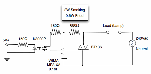
Having trouble with my triac switching circuit.
My circuit is based on the solid state relay circuit (using triacs) electronics-lab
I have tried 0.6W resistors and 2W
the 0.6 680 Ohm is fried instantly.
the 2W 680 Ohm smokes
It works with the 2W, it does switch on an off.
but its obviously drawing too much current across the resistors i cant figure out why.
There is sequencing circuit using flipflops using the the AC side could that be affecting it?
Or are my resistors just not limiting the current enough, a few people iv spoken to reckon i should have more like a 2.5K to replace the 680 Ohm
Here's my circuit as it stands. I hope to have 4 of these identical circuits running in parrallel from the same fused 240Vac source
