etiquoe
Member level 1
hi everyone...
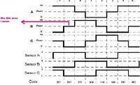
I have a 3-phase BLDC motor (24 V) with its dedicated driver. but i wanna make my own driver for the motor. it is sensored bldc motor. I have read some application notes and other kind of sources about controlling sensored BLDC motor and found that it is controled by 6 commutation steps. A fundamental BLDC motor (with 3 coils and 1 pair of poles) need 2 cycles of 6 commutation steps for 1 motor rotation. My BLDC motor has 12 coil, but i don't exactly know how many pairs its pole.
how can i know the number of pole?
with different number of coil and pole, does it need different number of cycle too?
i have checked the signal on the BLDC I/O pins when it's run by its original driver. its I/O pins contain Hall sensor feedback pins and phase pins.
here is the results:
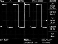
this is signal on the 3 pins which is known as phase pins. it is 24 v pwm signal.
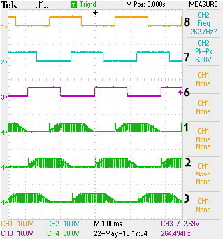
and this is signal on the phase pin too, when it's measured at the same time with the hall sensor pins. 1-3 are phase pins signals (24V), and 6-8 are hall sensor pins signals (5V).
there's different result on the phase pins. could anyone explain?
which one of the signals is input signal to the motor?
it's confusing for me, because i assume that the motor input signal should same as with what the application notes has explained, commutation signal.
anyone help please????
:?
best regards
I have a 3-phase BLDC motor (24 V) with its dedicated driver. but i wanna make my own driver for the motor. it is sensored bldc motor. I have read some application notes and other kind of sources about controlling sensored BLDC motor and found that it is controled by 6 commutation steps. A fundamental BLDC motor (with 3 coils and 1 pair of poles) need 2 cycles of 6 commutation steps for 1 motor rotation. My BLDC motor has 12 coil, but i don't exactly know how many pairs its pole.
how can i know the number of pole?
with different number of coil and pole, does it need different number of cycle too?
i have checked the signal on the BLDC I/O pins when it's run by its original driver. its I/O pins contain Hall sensor feedback pins and phase pins.
here is the results:
this is signal on the 3 pins which is known as phase pins. it is 24 v pwm signal.
and this is signal on the phase pin too, when it's measured at the same time with the hall sensor pins. 1-3 are phase pins signals (24V), and 6-8 are hall sensor pins signals (5V).
there's different result on the phase pins. could anyone explain?
which one of the signals is input signal to the motor?
it's confusing for me, because i assume that the motor input signal should same as with what the application notes has explained, commutation signal.
anyone help please????
:?
best regards