shengwuei
Newbie level 3
Dear all,
I have a transmit/receive system which is functionally work but have “damping(?)” problem on the receive path.
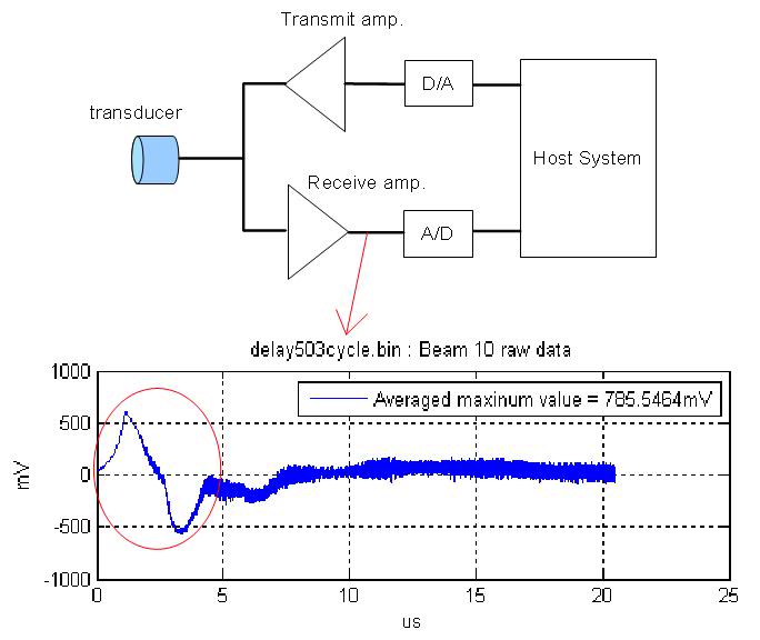
A simple system block diagram as shown below, a small but not negligible “damping” waveform can be observed both before and after receive amplifier(cycled in red as the figure below, this problem become serious after the amplification of receive amplifier).
I am not sure this is a “damping” problem or not because the frequency of the waveform is much lower than transmitted signal(50MHz). I've added some series capacitor to filter out the waveform but found its useless. Possibly there is still some high frequency part(close to the transmitting frequency) inside the waveform so a simple low-pass filter would not work. I guess I need to find the root cause of the “damping” problem so I can make it totally disappear in the receiving path.
Really have no idea about how to solve this problem, anyone can give me a clue on it ?
Appreciated for your input.
I have a transmit/receive system which is functionally work but have “damping(?)” problem on the receive path.
A simple system block diagram as shown below, a small but not negligible “damping” waveform can be observed both before and after receive amplifier(cycled in red as the figure below, this problem become serious after the amplification of receive amplifier).
I am not sure this is a “damping” problem or not because the frequency of the waveform is much lower than transmitted signal(50MHz). I've added some series capacitor to filter out the waveform but found its useless. Possibly there is still some high frequency part(close to the transmitting frequency) inside the waveform so a simple low-pass filter would not work. I guess I need to find the root cause of the “damping” problem so I can make it totally disappear in the receiving path.
Really have no idea about how to solve this problem, anyone can give me a clue on it ?
Appreciated for your input.