BillQ
Junior Member level 1
Hi,
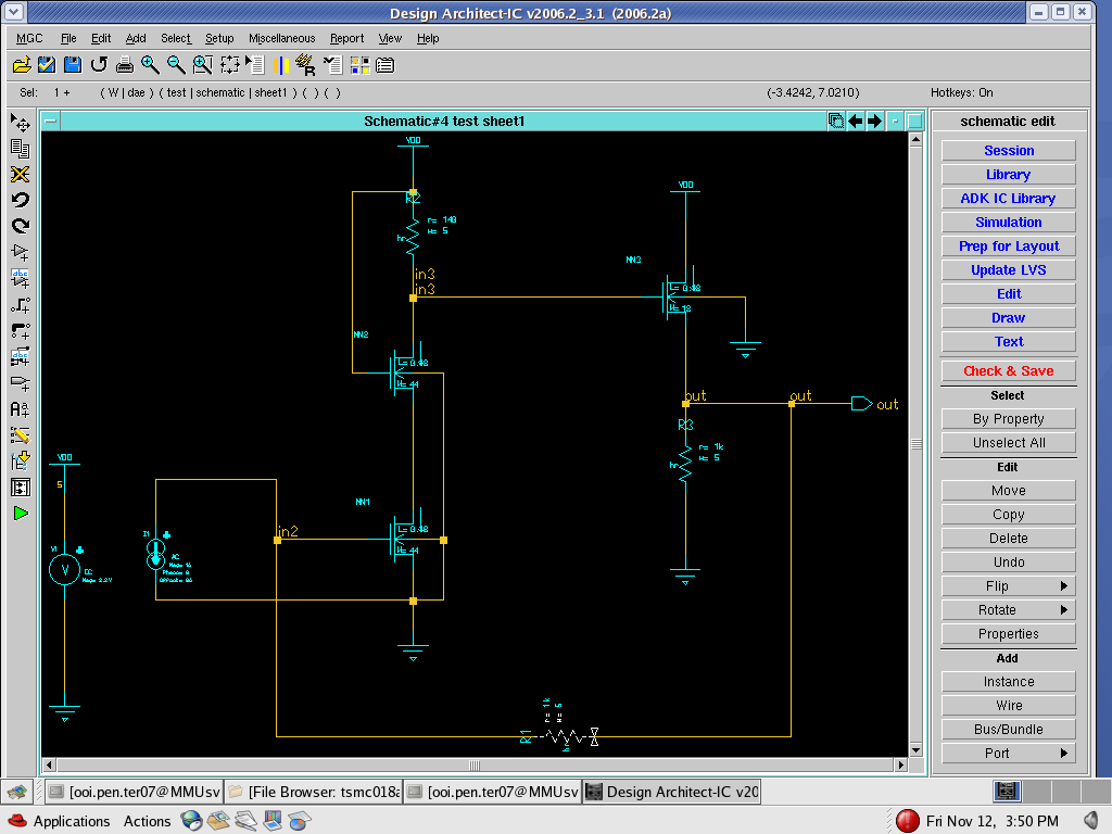
I am designing a transimpedance amplifier to convert an input current to an output voltage.
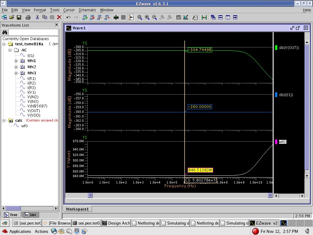
I have used an iprobe to simulate this amplifier, then I runned stb analysis in Cadence and got the bode diagramm for the GAIN(dB) and phase margin.
Is this gain value(for example 80dB) the closed loop gain of this amplifier?
If so, then the phase margin cann't be deduced from this bode diagramm, as for the phase margin, a plot of the open loop gain is needed?
Moreover, the transimpedance amplifier should have a gain with a unit of Ohm(V/A), this can't be converted into dB. So how can I describe the technical parameter GAIN of this amplifier, V/A or the simulated dB value?
Thanks!
I am designing a transimpedance amplifier to convert an input current to an output voltage.
I have used an iprobe to simulate this amplifier, then I runned stb analysis in Cadence and got the bode diagramm for the GAIN(dB) and phase margin.
Is this gain value(for example 80dB) the closed loop gain of this amplifier?
If so, then the phase margin cann't be deduced from this bode diagramm, as for the phase margin, a plot of the open loop gain is needed?
Moreover, the transimpedance amplifier should have a gain with a unit of Ohm(V/A), this can't be converted into dB. So how can I describe the technical parameter GAIN of this amplifier, V/A or the simulated dB value?
Thanks!