ulrikp
Junior Member level 3
- Joined
- Mar 1, 2010
- Messages
- 31
- Helped
- 3
- Reputation
- 6
- Reaction score
- 3
- Trophy points
- 1,288
- Location
- Copenhagen
- Activity points
- 1,568
Monitoring a reed switch
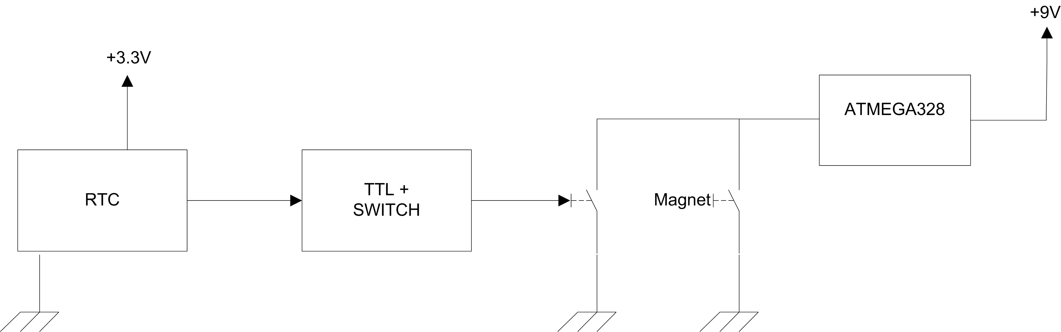
I have a battery driven device that is normally off and can be turned on by either a (mechanical) reed switch or an RTC connected to a mosfet gate. The two switches work on the same battery. The system wakes up once a day and does a job. I would like to have a way of monitoring if the reed switch closes while the system is on (ie. while the RTC controlled switch is closed).
Of course, I can put a second reed switch on there and connect it to an I/O pin on the microcontroller, but I'm looking for a smoother way. I use an ATMEGA 328 microcontroller. Hope someone has a good idea.
Best regards,
Ulrik
") _ exactly what your PIC likes.
_ exactly what your PIC likes.