Tricaltronics
Newbie level 2
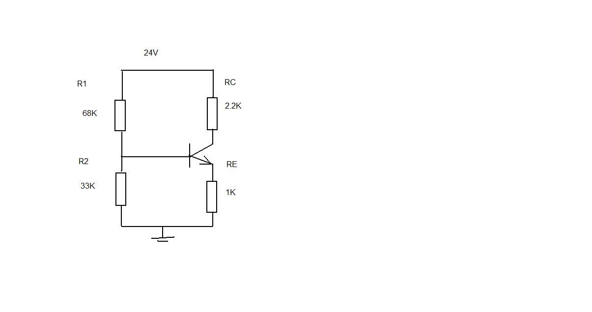
could anyone help with voltage divider bias.
need to find IC and VCE, if the following info is given:
VCC = 24V
BETA = 200
VBE = 0.7V
R1 = 68K
R2 = 33K
RC = 2.2K
RE = 1K
need to find IC and VCE, if the following info is given:
VCC = 24V
BETA = 200
VBE = 0.7V
R1 = 68K
R2 = 33K
RC = 2.2K
RE = 1K