Continue to Site

Welcome to EDAboard.com

Welcome to our site! EDAboard.com is an international Electronics Discussion Forum focused on EDA software, circuits, schematics, books, theory, papers, asic, pld, 8051, DSP, Network, RF, Analog Design, PCB, Service Manuals... and a whole lot more! To participate you need to register. Registration is free. Click here to register now.

Diode SMD Marking ID Help

Status
Not open for further replies.

jlocke

Newbie level 3
Joined
Feb 28, 2010
Messages
3
Helped
0
Reputation
0
Reaction score
0
Trophy points
1,281
Location
Upland, California
Activity points
1,306
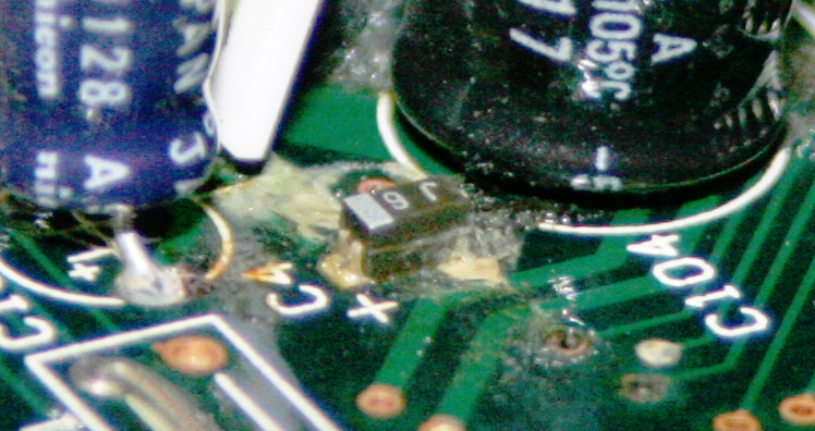
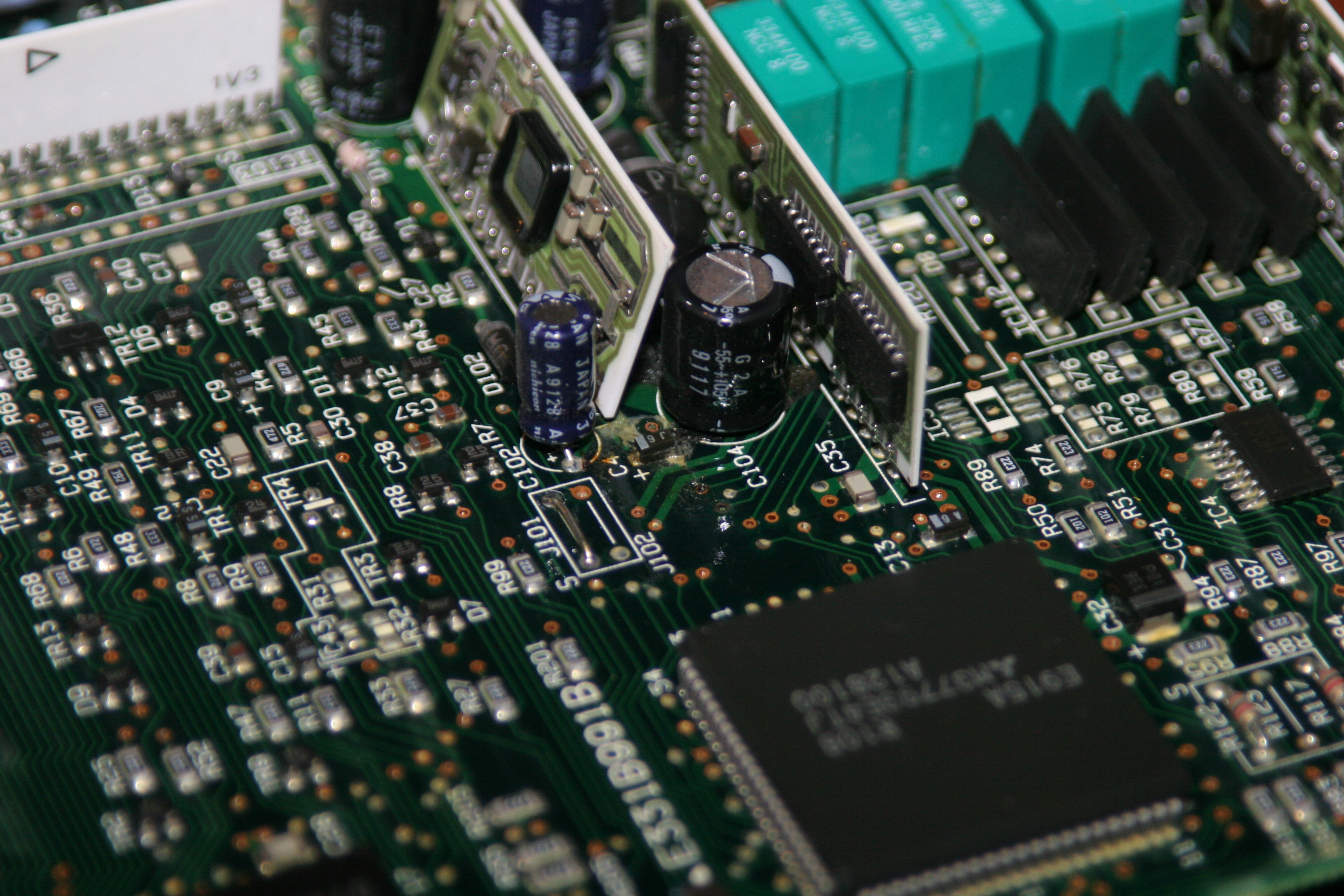
My ECU for my car had a capacitor leak and caused damage to the diode C4. Its marking is J6. I already replaced the capacitor but I am having a heck of a time locating a replacement diode. Any Ideas?


Hi,
Interessant as question!
C4 stays for capacitor, as the photo us displays too: I believe that its a Tantal_maybe a 6V3, 1 uF, size seems me 1206=it is realistic for 6.3V 1.0uF!!
Maybe, because coding J= 6V3, but usually should be after that not 6 to find, but more 605...anyway; not all producer are full standard conform.
Otherwise, what more a problem is:
the Vias, their are (minimum 3 pcs) ruined too & if its a multilayer board: you have to work_you must buildin some bridges (for example with Wire Wrap wires), but I think the 1uF canbe OK!
K.
 

Not sure if this matters...The board was built around 1990-1991 in most likely Japan.

I don't think Its a multi layer board, just double sided. I could be wrong. How ever I did shine a bright light I didn't see any traces besides the ones on the back.
 

OK,
but in all case - you must check for all dead (or maybe dead) vias & built in bridges for functioning...
To be sure do measurings pls with an Ohm meter check the lines over your "problematic" vias(you will find some broken:-(!), & you can change C14 for an 1.0...1.5 uF min. 6,3 V Tantal version...
K.
 

I completely agree to identify the part as a tantalum capacitor. You'll surely notice, that no diode in the circuit has a designator of Cxx,
but all capacitors have a C. To identify the correct value can be more difficult, J6 is a code that can mean a lot, so I would prefer to
determine the voltage rating from a circuit analysis. Why do you think the part is damaged, by the way?

Perhaps you should desolder it and check if it's still behaving as a capacitor.
 

Hi FvM,
Standard SMD "j" coding = 6.3 V....
The 6 as 1x 10^6 = 1uF, I think you can agree with that too?
k.
 

Voltage coding J=6.3V yes, but I never saw "6" for 1 uF, it can mean also something different.
 

When I was cleaning the electrolytes from the circuit board I accidentally flipped up C4 on end. So the end that is not showing is not connected to the board. There are no leads that I can solder to. They are all gone.

Added after 47 minutes:

I have been looking at Digi-Key but all the tantalum capacitor smd's that I see only have one lead. in my picture there are two coming out of the left side.

Could that just be a old style since they are almost 20 years old?
 

Lead style is manufacturer and type dependant. You'll find these "split" leads with some recent types as well. They don't have any
functional relevance. But voltage rating and possibly capacitance matters.

The tantalum capacitor may be simply connected in parallel to a large electrolytic capacitor. In this case, the voltage rating can be
easily determined and the capacitance isn't critical.
 

HI jlocke,

You can be sure, these is a Tantal with 2 electrodes(only question are >capacity & voltage); if you do magnifing the big picture= you can see the second pad soldered on the right handside & (below "J") and the Via in top of that is possibly the contact to the rest of PCB... The Vias red color means; it was etcehd & if the Tantal has not a contact onto the right side: is was etched from _ electrolythics fluids are enough acydic to make it(over time of course)!
Between C104 & J102 is the next Via eventuell critically etched, the other is to repair (I wrote over bridges their are to apply..:)
I can only propos for you; take pls C104 out too,; often are the solder plases in so a situation critical too: a cleaning & resoldering is sure needed or not bad!:)
K.

Added after 41 minutes:

Ahoi,
Yet found I a better(?) SMD coding side:
w*w.satcure-focus.com/design/page2.htm
So its clear; C4(J6)=2.2uF,6.3V
You have some S5 too, their are .47uF_but what kind of voltage?
SMD coding is every time chatastrofic unsistematcally maked, much verisons & often are markings with more meanings to identify...:-((
K.

Added after 9 seconds:

Ahoi,
Yet found I a better(?) SMD coding side:
w*w.satcure-focus.com/design/page2.htm
So its clear; C4(J6)=2.2uF,6.3V
You have some S5 too, their are .47uF_but what kind of voltage?
SMD coding is every time chatastrofic unsistematcally maked, much verisons & often are markings with more meanings to identify...:-((
K.
 

Status
Not open for further replies.

Similar threads

Part and Inventory Search

Welcome to EDABoard.com

Sponsor

Back
Top