gres
Full Member level 4
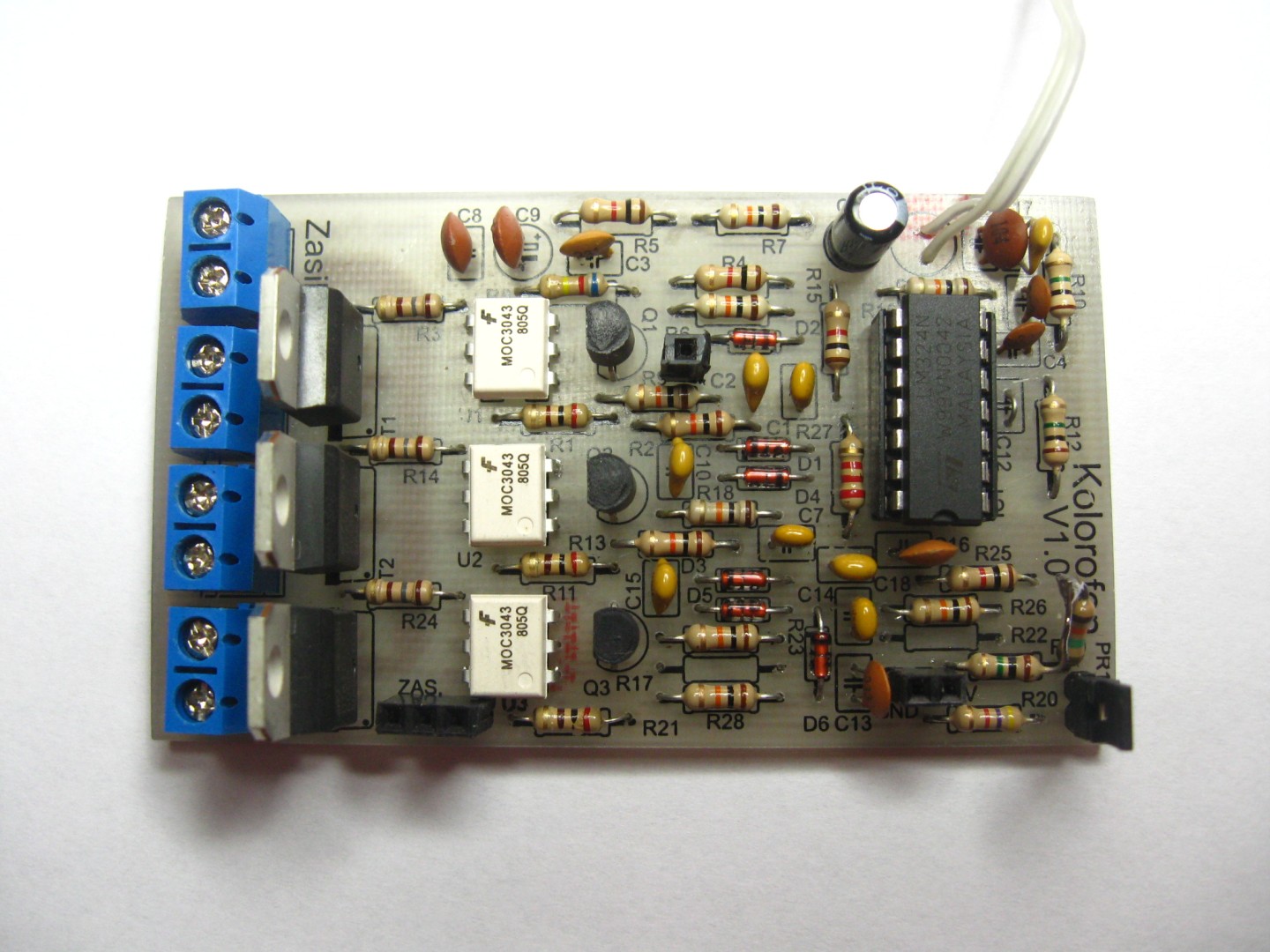
3 channels disco lights
Project based on diagrams from internet.
System description
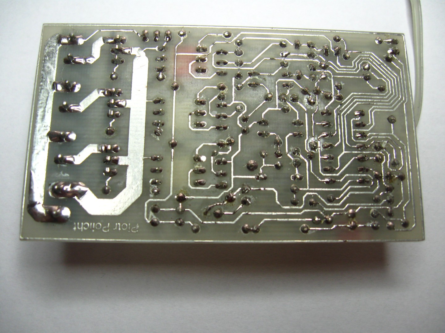
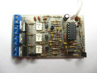
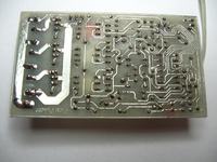
Heart of the system is LM324 cube that consist 4 operating amplifiers. Signal from microphone is gain by one of the amplifiers. Gain regulation is step via JP3 jumper. Condenser C12 secure next chips agains DC. Then signal goes to 3 active filters. Thanks to change condensers and resistors parameters in those filters we can match work frequency of each channel. Active filters deliver better channels separation then passive filters.Signal from filter is putting to BC547 transistor that steer the optotrac work. I used MOC3031 optotrac that consist in it's structure, detector of passing through zero. Thanks to that turnic on the triac have place only at phase passing throguht zero that prevension against noise to electric network.
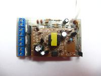
As a power supply i used USB charger ( I had bought at the internet). If you buy a few cost is really low. They have 500mA with 5V. Board is set specially for that power supply.
At https://www.elektroda.pl/rtvforum/topic1496893.html you can find original text with files to downlad:
Kolorofon.scg - disco lights scg
Kolorofon.brd - disco lights brd
Polaczone.pdf - board sample ready to print
Project based on diagrams from internet.
System description
Heart of the system is LM324 cube that consist 4 operating amplifiers. Signal from microphone is gain by one of the amplifiers. Gain regulation is step via JP3 jumper. Condenser C12 secure next chips agains DC. Then signal goes to 3 active filters. Thanks to change condensers and resistors parameters in those filters we can match work frequency of each channel. Active filters deliver better channels separation then passive filters.Signal from filter is putting to BC547 transistor that steer the optotrac work. I used MOC3031 optotrac that consist in it's structure, detector of passing through zero. Thanks to that turnic on the triac have place only at phase passing throguht zero that prevension against noise to electric network.
As a power supply i used USB charger ( I had bought at the internet). If you buy a few cost is really low. They have 500mA with 5V. Board is set specially for that power supply.
At https://www.elektroda.pl/rtvforum/topic1496893.html you can find original text with files to downlad:
Kolorofon.scg - disco lights scg
Kolorofon.brd - disco lights brd
Polaczone.pdf - board sample ready to print