Continue to Site

Welcome to EDAboard.com

Welcome to our site! EDAboard.com is an international Electronics Discussion Forum focused on EDA software, circuits, schematics, books, theory, papers, asic, pld, 8051, DSP, Network, RF, Analog Design, PCB, Service Manuals... and a whole lot more! To participate you need to register. Registration is free. Click here to register now.

-Problem with Counter-...Logical Circuit Design

Status
Not open for further replies.

spidey99

Newbie level 4
Joined
Jan 12, 2010
Messages
6
Helped
0
Reputation
0
Reaction score
0
Trophy points
1,281
Activity points
1,318
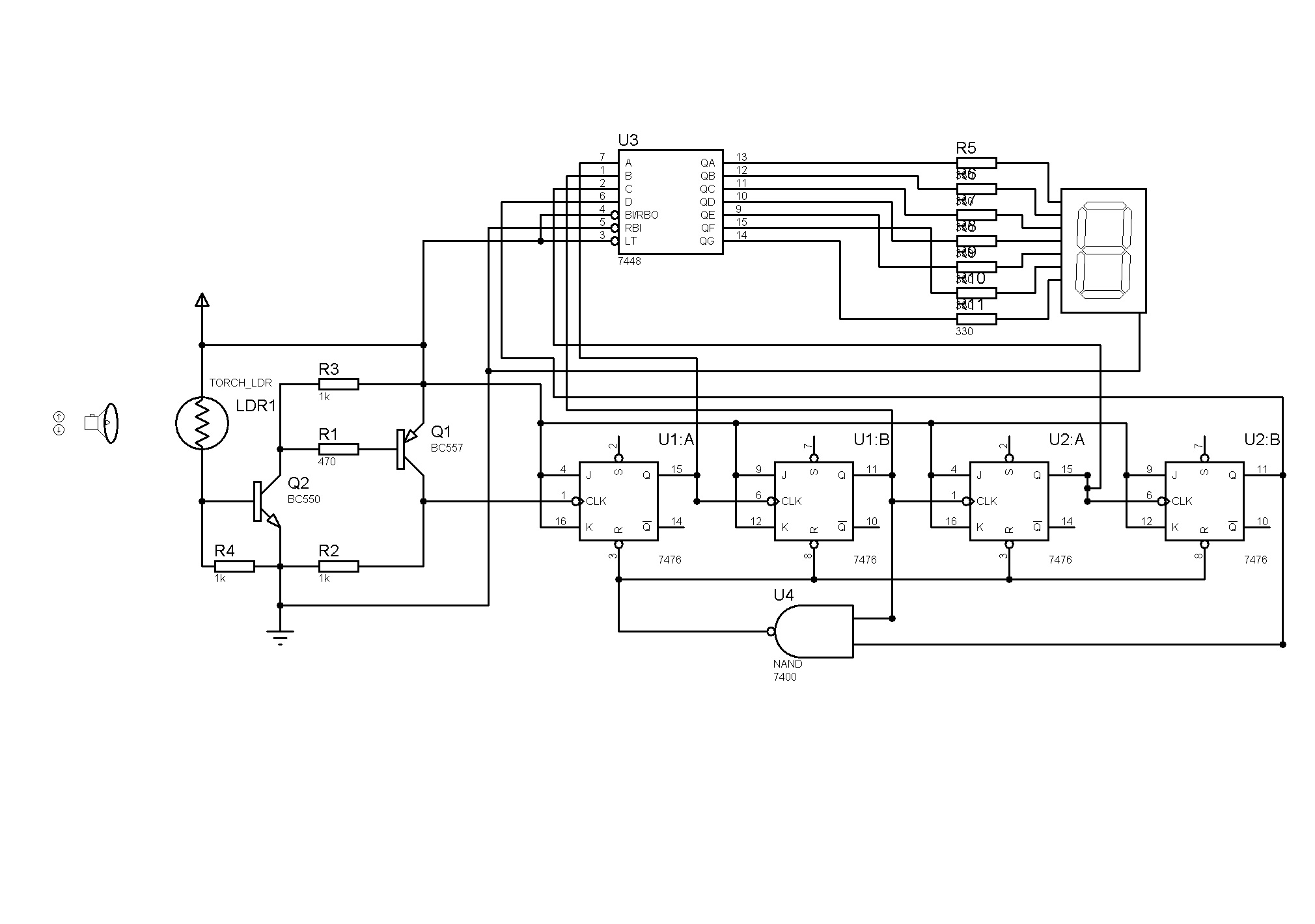
hi, i designed a counter with jk ffs. it count from 0 to 9 and resets at 10 to 0...
ffs get their clock pulses from circuit i designed with a LDR, aim of this, is to increase the counter by 1 when LDR s light goes off( when i put my hand on ldr, i should see that 7 segment increase by 1)
but when i energize the circuit, i see 0 at 7seg, and when i put a light towards ldr, 7seg becomes 1, but when i put off the light it goes back to 0 again...

awaiting your solutions...


Hi spidey99,
on the speedy checking-I cannot see some pwr-on RST, or preset to zero, am I right pls?
Means the arrow on LDR an +5V/Vcc?
K.
 

This is most likely due to the input of the 7400 nand gate (U4 lower pin) being pulled high permanently instead of being wired to pin 11 of U2B. Or you could have a faulty U2. Check to see if you get the correct logic (should be 0 on powerup) on input of the 7400 and pin 11 of U2.
 

@karesz; yes, arrow means +5 v, and as i said, the circuit works in isis...

@bongkk, well, even if i disconnect the 7400, there is no change in the behavior of the circuit...
 

Hi spidey99,
I would say, forget the LDR-transistor part and give such slower generator signal (i.e. KHz..) as clk for your circuit & test it with a scope...
K.
 

well, if i get rid of the ldr part, than there will be no speciality about the circuit...

can you suggest me another circuit with logical gates, if we can't make this one work???
 

Sorry, Im not involved with counters/digitals...
Your "hand effect" isnt only a "controlling through hum"?
Do you have such bypassing 100nFs on your ICs?...
K.
 

no, i don't have any capacitors installed...

should i?

i am thinking of installing 330 ohms to q outputs of jk ffs and connecting them to the (-) i hope it helps...
 

Hi spidey99,

I'm not sure, but try these:
1. Do not float the SET pins. Tie them to Vcc.
2. Try to use a monostable in between the transistor output and input to FF.You may be getting too many pulses at the output of transistor.
3. Use a low pass filter with the LDR. Simply connect a 1uF capacitor across R4.

Best wishes!
 

thanks matbob,
-what do you mean with monostable? do you think a schmitth trigger work that way?
-should i connect the capacitor in series with r4 or parallel?
 

Hi spidey,

Connect the capacitor parallel to R4. Just search in GOOGLE what is a monostable and its purpose.Schmitt trigger is different and cannot be used in place of a monostable.
 

ok, got it, so we will just trigger the 555 to generate a square clock signal?

nice idea though...
 

Status
Not open for further replies.

Part and Inventory Search

Welcome to EDABoard.com

Sponsor

Back
Top