gres
Full Member level 4
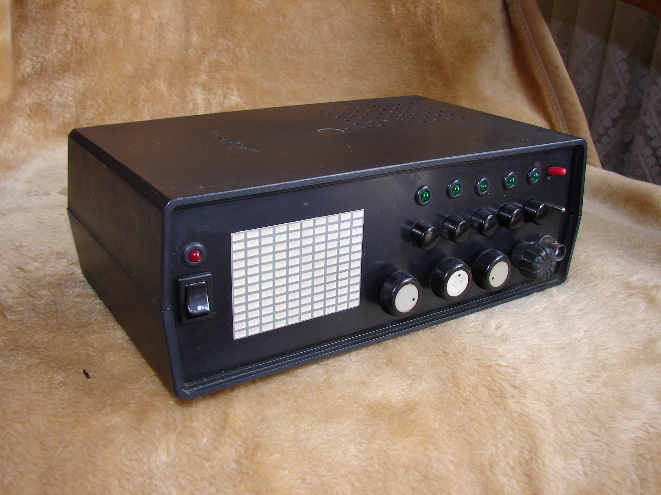
I would like to present amateurs Project of oscilloscope built on LED matrix. It’s a first “fast built” version, and before it was oscilloscope, it had been analyzer of acoustic spectrum. I was thinking what else can be displayed at LED matrix, and to my mind come an idea to rebuilt chipset and make oscilloscope. After some time I made synchronization system, and shell for oscilloscope.
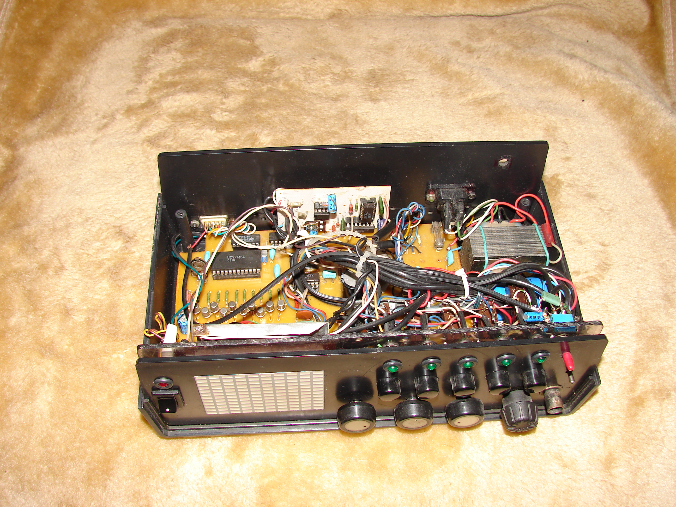
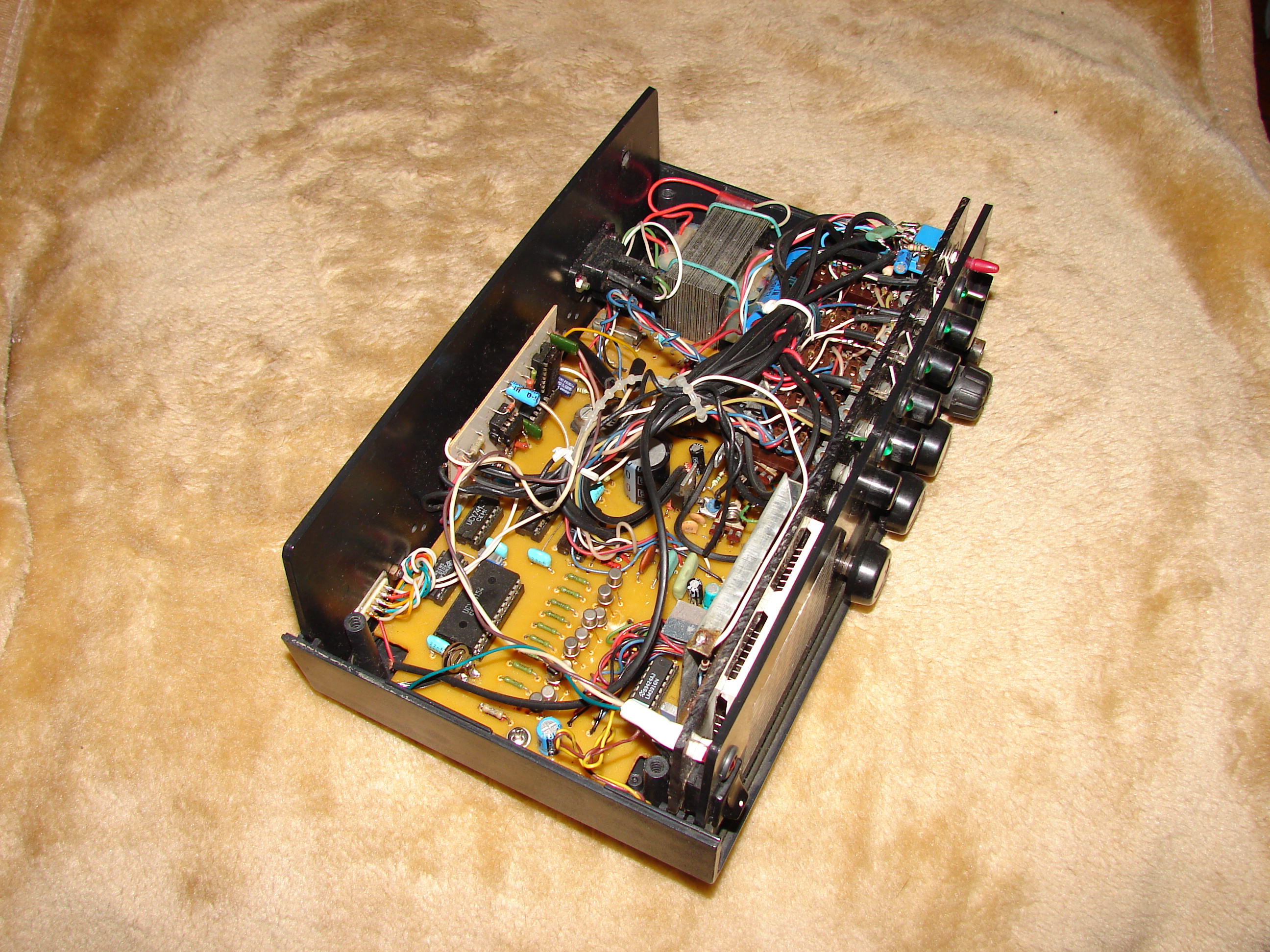
Elements of oscilloscope are: amplifier of input signal TDA2030, from vertical deflection modulation, from horizontal deflection modulationUCY74154, into that I added synchronization system and sweep generator US4, US5, US6. To input of oscilloscope come signal, that is magnify by TDA2030 system and thanks to potentiometer P3 we can magnify signal, and thanks to S6 switcher we can enter constant component to input of oscilloscope. Of course instead of TDA2030 should be another amplifier like 741 but I had TDA2030 at my drawer. There are more “mistakes” like this, but as I said it ‘s jut a “fast built version”. For the example trigger. I put it because I had problems with stability of synchronization system, of course you can made synchro system better, but trigger fixed all problems. The same with resistors for constant component correction – important is that it work. Red diodes are plugged to comparator output that have synchronization function, effect is that at display we can see wide of amplitude. Into system I plugged RS232 connector ( not present at schematic – I add it alter) that is plugged to demultiplexer UCY74154, I use it to experimental targets, at the moment, thanks to right attachment, it works like a acoustic analyzer.

Oryginal text at
https://www.elektroda.pl/rtvforum/topic1480650.html
")