Continue to Site

Welcome to EDAboard.com

Welcome to our site! EDAboard.com is an international Electronics Discussion Forum focused on EDA software, circuits, schematics, books, theory, papers, asic, pld, 8051, DSP, Network, RF, Analog Design, PCB, Service Manuals... and a whole lot more! To participate you need to register. Registration is free. Click here to register now.

Help me with a clapp oscillator design

Status
Not open for further replies.
capacitor doubt

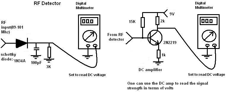
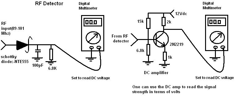
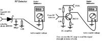
here i have made a RF detector,i think it works fine,what do u say
 

Re: capacitor doubt

The first part of the schematic is OK but the amplifier is doubtful. The bias resistors will upset the detector operation. Note also that it inverts, more signal = lower collector voltage.

It will probably be more sensitive if you use a Germanium diode instead of a Shottky one, they tend to have a lower conduction point and better HF response.

Also note that construction of the detector is critical, even small wire lengths will upset the readings.

Brian.
 

capacitor doubt

ya,but i will bias the base of the transistor with 1.5V,as now its it is biased with 3.7V,it will not be sensitive,if i bias it with 1.5V,it will get more sensitive,*(when the input signal exceed 1.5V it will get amplified)right?

Added after 1 minutes:

and i am going to use a schokkty diode like 1N6263 or
1N5711.
now that diode resolves the problem
 

Re: capacitor doubt

Not quite.

The diode will have a reverse voltage across it from the bias network, until you overcome that AND Vf of the diode it will not conduct. So you need (with your values shown) about 4V of signal before you measure anything.

Germanium diodes will perform better at high frequencies than Shottky silicon ones, although the diodes you suggest are for high speed switching, they are not best for VHF and above small signal rectification.

You will probably get better results if you remove the 15K resistor, short out the 1K resistor, and connect the diode where the 6.8K resistor is. Feed the signal through a small capacitor directly to the transistor base. That will let the transistors own B-E diode junction do the rectification and eliminate the voltage drops. Still far from perfect but better than what you have.

Brian.
 

capacitor doubt

betwixt said:
Not quite.

The diode will have a reverse voltage across it from the bias network, until you overcome that AND Vf of the diode it will not conduct. So you need (with your values shown) about 4V of signal before you measure anything.

Germanium diodes will perform better at high frequencies than Shottky silicon ones, although the diodes you suggest are for high speed switching, they are not best for VHF and above small signal rectification.

You will probably get better results if you remove the 15K resistor, short out the 1K resistor, and connect the diode where the 6.8K resistor is. Feed the signal through a small capacitor directly to the transistor base. That will let the transistors own B-E diode junction do the rectification and eliminate the voltage drops. Still far from perfect but better than what you have.

Brian.
u said to "Feed the signal through a small capacitor directly to the transistor base. "
but a capacitor block the DC signal and let the AC signal,and only DC signal comes out of the diode.

Added after 17 minutes:

and here i have used a germanium diode as u said ,a "1N34A" please check it and tell me if it has any errors


Added after 16 minutes:

or will this work?
 

Re: capacitor doubt

You are forgetting that the internal structure of a transistor has a P-N junction between the base and emitter pins so it 'looks' like a diode to the signal coming in.

It will derive it's own base current by rectifying the signal so you do not need a diode as well. You might be able to slightly improve its sensitivity by adding a resistor from the base to the supply but it should be a very high value so it provides only a tiny current to help bring the transistor nearer conduction. I would suggest trying 4.7MΩ as a starting value, making it too high will reduce it's effect, making it too low will hide the measurement of small signals.

Note that if you use this idea, you should connect the emitter directly to ground or its resistor will be in series with the B-E diode.

The LM386 is not suitable as an op-amp, it is designed as an audio power amplifier and has poor linearity and voltage swing at its output. If you really want to use an op-amp, use a modern one and connect it in precision rectifier configuration so you can measure right down to zero signal with good linearity.

Brian.
 

capacitor doubt

can u tell me a op amp which can amplify DC and which is in active production please

Added after 7 minutes:

and can this block RF(95Mhz) from entering the power supply,is the value of the inductor correct!


Added after 31 minutes:

here i have used a BC109 please tell me does it work fine,when the output of the detector is connected to the input of the amplifier,it forms a voltage divider of 1.5V to the base,if there is any problem in it ,please please please guide me to correct it
 

Re: capacitor doubt

Both wrong!

I think you are missing the point completely.

Your first schematic does nothing useful. Why do you want to feed the oscillator into the power supply in the first place? It is good practice to filter the supply lines but all you need is a small choke (15uH will do at that frequency) and a capacitor of 10nF at each end of it to ground. It goes in-line with the 12V to the whole circuit. You should have a voltage regulator with it's own filter capacitors for the oscillator stage alone.

The BC109 will not work properly. For a diode to conduct you have to make the anode more positive than the cathode (for the purists reading this, I'm excluding Gunn and bulk effect diodes from this!). In your schematic, you have the cathode raised to about 3V by the transistor base components. So to make it conduct you have to put more than 3V + Vf (about 3.5V) on it's anode. This is probably more than the circuit is capable of producing so you may not see any reading at all. think of it as being a voltmeter that doesn't start to measure until you have 3.5V across it's leads, it wouldn't be much use for measuring low voltages!

If you want to use an op-amp , I suggest something very inexpensive like a TL071.

Brian.
 

capacitor doubt

the RF choke is to block RF from the oscillator to the power supply and other parts of the circuit,i asked u the value of the inductance to block the RF,here in this circuit u can see a choke in the oscillator,and u said 15uH is fine to block 95Mhz,are u sure


Added after 1 minutes:

i have made it 100uH but its toooo big,but as u said 15uH will do fine.please check it out

Added after 2 minutes:

2)and u said" The BC109 will not work properly. For a diode to conduct you have to make the anode more positive than the cathode (for the purists reading this, I'm excluding Gunn and bulk effect diodes from this!). In your schematic, you have the cathode raised to about 3V by the transistor base components. So to make it conduct you have to put more than 3V + Vf (about 3.5V) on it's anode. This is probably more than the circuit is capable of producing so you may not see any reading at all. think of it as being a voltmeter that doesn't start to measure until you have 3.5V across it's leads, it wouldn't be much use for measuring low voltages! "


but the transistor base is biased to 1.5V not 3V,if u connect the output from the detector to the DC amp base,the 15K and the 3k will bias the transistor base to 1.5V not 3V,please check it once again

Added after 1 hours 55 minutes:


here in this schematic the base is biased by 0.5V ,can the amp amplify the 1Volt DC.
 

Re: capacitor doubt

Even if the transistor had 0.5V on it's base, you would still need about 1V of signal before it STARTED to measure any voltage. The point I am making is you are trying to measure a small voltage with a circuit that has a low voltage threshold before it starts to show. Your signal is almost certainly too small to read on the meter. What you really want is to minimize the amount of voltage needed to make a measurement show.

I make a suggested change to your schematic in my diagram. The three lower sections are alternative ways of measuring the antenna voltage. I'm sorry the quality is bad, I drew it on scrap paper and photographed it with my mobile phone!

Brian.
 

capacitor doubt

its a colpitt's oscillator

Added after 3 minutes:

and its similar to mine,only difference is that my design has hartely oscillator,and at the end u have a Pi tank,can u tell me the value for the L and C of the Pi tank

Added after 3 minutes:

and betwixt thank u

Added after 29 minutes:

and i want to make a oscillator of 44KHz ,as its a audible frequency(am i right) ,can i generate 44KHz signal with a RC oscillator and feed it to the audio input to the Fm TX and at the receiver i can demodulate the signal and convert the 44KHz AC into DC with a 1N34A and amplify it and connect it to a relay and use it as a switch,is my idea practical and do u think it works?
 

capacitor doubt

44kHz is much too high to be audible (the highest audible frequency heard by young people is 20kHz).
The de-emphasis (high frequencies cut) in all FM radios will reduce 44kHz to almost nothing.

Stereo FM radios severely cut frequencies above 15kHz so that they do not activate the 19kHz stereo pilot detector and mess up the 23kHz to 53kHz stereo sidebands.
 

Re: capacitor doubt

Audioguru is absolutely right. Why are you choosing 44KHz anyway, the cheapest solution to this is to use a DTMF generator at the transmitter and a DTMF decoder at the receiver. That way you do not have to use any filtering and you get 16 different channels to use instead of one.

I have to comment though, a few years ago when I was "4x" years old, I worked in a factory that had an ultrasonic plastic welder. Nobody seemed to notice it except me. Whenever it was used I climbed the walls in pain, it used to REALLY irritate me while everyone around me couldn't understand what was wrong. I think it ran at 20KHz and pumped a few hundred Watts into a titanium horn. Maybe I've just got sensitive hearing but I can also hear the 19KHz stereo pilot tone on some FM receivers.

Brian.
 

capacitor doubt

When I was a teenager I heard the deafening sound from an "ultra-sonic" burglar alarm. They left it turned on all the time since its frequency was so high that "nobody" could hear it.

I heard distortion and very high frequency resonance in amplifiers and loudspeakers at work but nobody else did.

But I am not a dog and I am not a female.
 

capacitor doubt

but i need to generate a constant sine wave,can u tell me the audio which comes out from a computer audiuo jack which is connected to the speaker,what is the frequency of the audio.

Added after 1 minutes:

i think 41Khz,is it right or wrong

Added after 4 minutes:

for example if i transmit audio from my computer and give it as input to a FM tx,but the varing signals modulate the frequency of the oscillator,but i need the input to be identical and constant and unchanged and undamped.so please tell me the frequency of the audio frerquency from the audio jack,and in most of the FM players or winamp players its writtens a 44Khz.

Added after 1 minutes:

first i want to use a RC oscillator, to generate the low frequency (Khz)when i become succesful ,then as u said i will use a DTMF generator..
 

Re: capacitor doubt

The audio from a computer audio jack is at whatever frequency you like. The frequency or 'tone' is what makes the speech or music you listen to. It probably spans a range of 10Hz to 20KHz and may contain complex mixes of several frequencies at once. That's what sound is!

You are confusing the audio you hear with the sampling rate which is often 44.1KHz. This is not what comes from the audio jack, it is the number of times a digital number is converted to an analog voltage per second.

Consider what you are planning: if you want to operate something when a tone is received by rectifying it to detect it's presence, what happens when the transmitter is not turned on? Hint: tune an FM radio to a gap between stations, do you hear nothing or do you hear hiss? What is the difference between rectifying a tone and rectifying hiss? Is there a difference?

Audioguru, there was a device called a 'Mosquito' used near here recently. It was a coarse high pitched sound generator designed to discourage young people from gathering outside shopping malls. The idea was that nobody over a certain age would hear it but it such is the crazy law here, they were ordered to remove it because it violated human rights!

Brian.
 

capacitor doubt

Silverthunder did not understand what I said about de-emphasis and stereo filters in FM radios.

I have heard about "The Mosquito" but since many young people have been deafened by playing their ipods too loud then it didn't always work.

Classical music playing with very low distortion also shoos away young people.
 

capacitor doubt

friends can u tell me the bias for the transistor base(T1,T2,T3) are right,will they work at that voltage to the base..
and on what factors u depend to select the voltage to the base..


Added after 2 minutes:

the T1 base is biased by 3.7V and t2 is biased by 4.8V and T3 is biased by 6V,is it reasonable

Added after 2 hours 18 minutes:

and please tell me are those bias(voltage divider) resistors are correct,or will it damage the transistors,and does it work,


pleaaaaaaaaaaaaaase tell me does those T2,T3 and T4 amplifier work,with those values,pleaseeeeeee pleaseeeee

Added after 37 minutes:

and friends here i made a sample circuit,to understand and learn.so please tell me does it work and is there any errors and if there please tell me to correct it.pleaseee
92_1262119447.jpg
 

Status
Not open for further replies.

Similar threads

Part and Inventory Search

Welcome to EDABoard.com

Sponsor

Back
Top