Continue to Site

Welcome to EDAboard.com

Welcome to our site! EDAboard.com is an international Electronics Discussion Forum focused on EDA software, circuits, schematics, books, theory, papers, asic, pld, 8051, DSP, Network, RF, Analog Design, PCB, Service Manuals... and a whole lot more! To participate you need to register. Registration is free. Click here to register now.

Help me with a clapp oscillator design

Status
Not open for further replies.
capacitor doubt

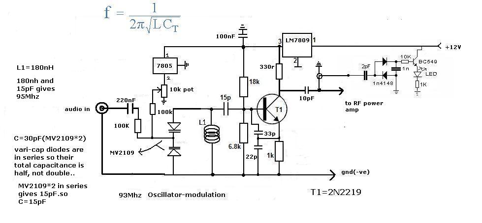
The 7805 regulator is rated at 1A but in this simple circuit its load current is zero. Why not use a little 78L05 (rated at 100mA) instead?

Voltage regulator ICs are always used with an output capacitor to ground. 0.1uF is used in the datasheet. Your 7805 does not have an output capacitor.

I didn't look at the oscillator parts.
 

capacitor doubt

please tell me is there any errors in oscillator part
 

capacitor doubt

Please build the simple circuit, see how poorly it performs, tell us how bad it is then go away.

You don't need 6 threads and a hundred posts for such a simple circuit. Plus all the posts from us.
 

capacitor doubt

Audioguru said:
Please build the simple circuit, see how poorly it performs, tell us how bad it is then go away.

You don't need 6 threads and a hundred posts for such a simple circuit. Plus all the posts from us.
dude if u are irritated dont help me out ,its OK.but dont insult!

Added after 53 seconds:

as u say from now i will not post too many threads
ok!
 

capacitor doubt

guys here is a band pass filter " https://en.wikipedia.org/wiki/File:Bandpass_Filter.svg "
i want to filter 95Mhz from a oscillator! so should be the resonance of tank circuit of the filter should
be 95Mhz in order to pass only 95MHz...
for example 180nH and 15pF makes 95Mhz...so the values of the three inductors should be 180nH and the all three capacitors be 15pF...am i right.please help me!
 

capacitor doubt

95MHz is a single frequency. A bandpass filter passes a range of frequencies.

You don't want a bandpass filter, you want only an LC sharply tuned filter.

But again, you forgot to include stray capacitance of the wiring in your calculation so the frequency will be much lower than 95MHz.
 

Re: capacitor doubt

aj_silverthunder, nobody is insulting you. However, you keep making small changes and asking "will this work" then making another change and asking again. All the time you ignore the advice people are giving you.

Please understand:

1. A stable oscillator is immune to outside influences - so you need to isolate the effects of changing output loads.

2. Choose the right device for the application in hand - a 1Watt loudspeaker driver is not the device you need to modulate a 1mW oscillator. You need a voltage amplifier, not a power amplifier.

3. An oscillator will not work if you short out its tuning components

4. The idea of varactor (varicap) diodes is their capacitance varies according to the voltage across them. You need to set the voltage so it can swing up and down according to the modulation.

5. If you wire a bandpass filter directly to an oscillator it will at best pull it way off frequency but is more likely to stop it oscillating altogether. You need to buffer the oscillator so it's resonant circuit and the bandpass filer cannot interact with each other.

Please listen to the good advice people are telling you and try to learn why they are critical of your design. You will learn nothing by randomly changing your schematic and re-asking the same questions.

Brian.
 

capacitor doubt

thank u brian

Added after 5 minutes:

so to filter the 95Mhz frequency a parellel LC filter with a resonance of 95Mhz should be used! and the the output from the oscillator should be fed to the LC filter,

Added after 2 minutes:

as i have read somewhere,the feedback is given through 22pF capacitor!am i right!


Added after 32 minutes:

please tell me does this circuit have feedback or not..
and if does not have feedback ,will it oscillate!
i am really confused about feed back!
 

Re: capacitor doubt

You are doing it again!

1. Forget the 7805 regulator - you already have a stable 9V at it's input so why bother with it. Take it out and connect the top of the 10K potentiometer to the output of the 7809 via an 8.2KΩ resistor.

2. Do not connect the output directly to a bandpass filter - you ignore what I said earlier, it will not work. You have to use a stage of isolation (a buffer stage) between the output of the oscillator and the BPF. As Audioguru states, if you have a single frequency there is no point in using a bandpass filter, use an LC matching network which not only gives a cleaner output, it will likely give you more power by matching the load impedance as a bonus. The buffer stage should be a transistor amplifier with high input impedance.

Yes, the 22pF and 33pF capacitors form the feedback network. Please read about oscillators to understand how they work.

You also need a capacitor across your incoming supply or the 7809 may not regulate properly.

Brian.
 

capacitor doubt

i started to study electronics from about 8 months,for the first time i have designed my own circuit! please check it out..
please tell me does it work!
and does that LC filter the 95Mhz perfectly!
i am not experienced as u but i am trying my level best!


Added after 19 minutes:

in this circuit assume the oscillator transistor is 2N2219,the circuit is powered by 12 VDC,the MAXIMUM emitter-base voltage is 5 Volts... so if the value of r4 is 10K and r3 is 10K,it creates a voltage of 6 Volts,if that 6V goes to the base of the transistor wont it damage the transistor!
 

Re: capacitor doubt

Remove the 5V regulator and put the 9V one back in. You need this to ensure the oscillator supply voltage stays stable.

If the bottom 10K potentiometer is not set with its wiper to ground, the tuned circuit will do nothing and the oscillator will stop.

The varactor diode is DC shorted by the tuning coil so it is impossible to fix a voltage across it.

The capacitor across R9 will reduce the signal level - which is probably not what you want to do.

R14 and R15 do nothing whatsoever - remove them.

Consider removing the whole output network and replacing it with a pi network which will give better harmonic rejection, better impedance matching and uses fewer components.

Place an RF filter capacitor across the 'audio in' socket to limit the passage of RF in and out of it.

Your transistor bias calculation is nonsense, the voltage you talk of is between the base and emitter which is set by Vbe and usually around 0.6V.

Brian.
 

capacitor doubt

The max allowed voltage for the reverse-biased emitter-base junction is 5V. But in your circuit and most other circuits it never gets reverse-biased because it is always forward-biased.
 

capacitor doubt

should the wiper connected to the ground and the other terminal should be connected to the oscillator.


how to make that varactor work properly!

i have placed a capacitor at the audio input!
what do u mean by RF filter capacitor.

what does that voltage divider do(potential divider)
at the oscillator transistor! does it limit the input voltage to the base of the transistor

Added after 13 minutes:

but does that LC filter also work!

Added after 34 minutes:

how do u find out the maximum breakdown voltage of a transistor..
like the maximum breakdown voltage for base, max breakdown voltage for emitter, and for the collector!
so that i can apply appropriate voltage to the base ,emitter and collector!
 

capacitor doubt

I think there should be a special website for these NOOBs who know nothing about electronics.
 

Re: capacitor doubt

betwixt said:
Remove the 5V regulator and put the 9V one back in. You need this to ensure the oscillator supply voltage stays stable.

If the bottom 10K potentiometer is not set with its wiper to ground, the tuned circuit will do nothing and the oscillator will stop.

The varactor diode is DC shorted by the tuning coil so it is impossible to fix a voltage across it.

The capacitor across R9 will reduce the signal level - which is probably not what you want to do.

R14 and R15 do nothing whatsoever - remove them.

Consider removing the whole output network and replacing it with a pi network which will give better harmonic rejection, better impedance matching and uses fewer components.

Place an RF filter capacitor across the 'audio in' socket to limit the passage of RF in and out of it.

Your transistor bias calculation is nonsense, the voltage you talk of is between the base and emitter which is set by Vbe and usually around 0.6V.

Brian.
i think the tuning coil cant short the varactor,and the varactors works! how can the coil short the varactor!
 

capacitor doubt

Of course the tuning coil shorts the varactor. The coil is just a piece of wire. There must be a coupling capacitor between them to block the DC from the varactor from being shorted by the coil.

Your original circuit has the tuning voltage applied to the varactors but not to the tuning coil.
 

capacitor doubt

i have made a oscillator around colpitt oscillator,i feel it works fine what do u say..please give me some suggestions to make it more fine


Added after 9 minutes:

please check the modulation part(varactor,voltage to the varactor part)..please
 

Re: capacitor doubt

I suggest you download a free simulator and then you can tell us if it works...

**broken link removed**
 

capacitor doubt

its a simple circuit ,it dont need any simulation,my only doubt is that is the ground connection of the oscillator in this circuit is correct,because i have seen colpitt oscillator which has ground in between the two capacitors!
 

Re: capacitor doubt

Okay, but I will say that I have simulated much simpler circuits and been surprised by the results. Best of luck...
 

Status
Not open for further replies.

Similar threads

Part and Inventory Search

Welcome to EDABoard.com

Sponsor

Back
Top