mylove
Newbie level 1
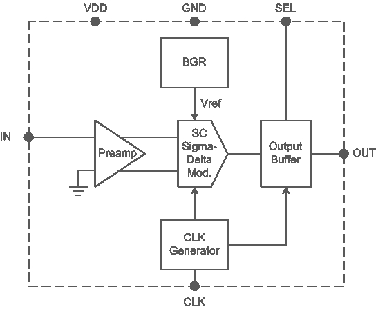
I design a SC Sigma-Delta ADC for audio application as showed in the attached Figure. The ADC is designed to work under supply voltage range of 1.6V to 3.3V and clock freq. of 2.56MHz. I have fabricated 2 chip for testing.
- Chip01 with the VDD/GND are shared for analog and digital sub-locks. It works well with VDD = 1.6 ~ 2.2 V and Fclk =2.56MHz. If I increase Fclk>3.5MHz, it works well for full range supply (1.6~3.3V).
- Chip02 with uses LDO regulator to separate the supplies for analog and digital sub-locks. It doesn't work with Fclk =2.56MHz for any VDD. If I increase Fclk>4.5MHz, it works well for full range supply (1.6~3.3V).
The core circuits are the same for the 2 chips except some different coefficients.
Anyone know the reasons, please tell me! Thank you very much!