PA4TIM
Full Member level 2
- Joined
- Aug 1, 2013
- Messages
- 120
- Helped
- 34
- Reputation
- 68
- Reaction score
- 34
- Trophy points
- 28
- Location
- the Netherlands
- Activity points
- 1,035
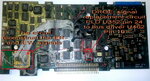
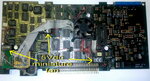
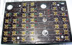
Finally, the project is finnished. The 2710 is now working like it should, no errors.
The complete story: with photos: https://www.pa4tim.nl/?p=4522
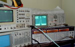
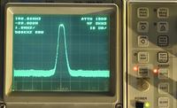
The first measurement after repair:
The complete story: with photos: https://www.pa4tim.nl/?p=4522
The first measurement after repair: