Continue to Site

Welcome to EDAboard.com

Welcome to our site! EDAboard.com is an international Electronics Discussion Forum focused on EDA software, circuits, schematics, books, theory, papers, asic, pld, 8051, DSP, Network, RF, Analog Design, PCB, Service Manuals... and a whole lot more! To participate you need to register. Registration is free. Click here to register now.

rpm-interfacing microcontroller circuit: engine's spark coil

Status
Not open for further replies.

Faizan Jawaid

Full Member level 3
Joined
Jul 17, 2008
Messages
189
Helped
23
Reputation
46
Reaction score
5
Trophy points
1,298
Location
Karachi, Pakistan
Activity points
2,336
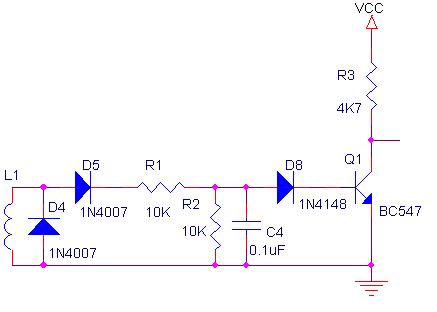
I have car with CDI type ignition system. I need to detect the rpm of the engine through electrical means. How do I interface a microcontroller circuit with the engine's spark coil.

regards
 

Re: engine rpm!

Hai

Use a wire (dont connect any where) coiled around the spark plug wire and it acts like an antenna

MicroCon
 

engine rpm!

Do impliment and practically check the sugession by "microcon555". It works and i have used the same technique many times without any problems. If you get a distorted pulse then we can think about solving that. Coz when you get pulses transfered from such high voltages on a spark plug wire, there is no other voltage in the vehicle to create distortion and even if you get, it will not be that high as the pulse you get. Good luck.
 

Re: engine rpm!

Use the below circuit to clean the pulses.
38_1244969036.jpg

Cheers

Ravi
 
Re: engine rpm!

Spartplug or the wire going to the sparkplug. L1 will just pick up the ignition pulses.

Cheers

Ravi
 

Re: engine rpm!

ravimarcus said:
Use the below circuit to clean the pulses.
38_1244969036.jpg

Cheers

Ravi

I made some modifications to the circuit. At the collector of the transistor I hooked up an LED with 1K series. The circuit wasn't working at all, the LED wasn't bliniking. Then i removed the 0.1uF capacitor and replaced with a 33pF Cap.

LED was blinking but very light as the spark is induced in the plugs.

so should i amplify the signal at collector to drive the optocoupler?
 

Re: engine rpm!

Faizan Jawaid said:
I made some modifications to the circuit. At the collector of the transistor I hooked up an LED with 1K series. The circuit wasn't working at all, the LED wasn't bliniking.
Thats because you were driving too low a current to the LED.

Faizan Jawaid said:
Then i removed the 0.1uF capacitor and replaced with a 33pF Cap.
These values can be changed as required.

Faizan Jawaid said:
LED was blinking but very light as the spark is induced in the plugs.
so should i amplify the signal at collector to drive the optocoupler?
If the LED is blinking, then replace it with the opto LED,

Cheers

Ravi
 
Re: rpm-interfacing microcontroller circuit: engine's spark

Ravi,

Would this circuit work the same way if I swapped the BC547 for an op-amp/comparator, connecting the output of D8 to the inverting input and some reference voltage to the non-inverting input? I need to generate a square pulse from the RPM pickup coil, but my board was designed around a MC34074 op-amp, I wonder if this IC would be fast enough to handle the RPM pulse width...?
 

Re: rpm-interfacing microcontroller circuit: engine's spark

rbfowler9 said:
Ravi,

Would this circuit work the same way if I swapped the BC547 for an op-amp/comparator, connecting the output of D8 to the inverting input and some reference voltage to the non-inverting input? I need to generate a square pulse from the RPM pickup coil, but my board was designed around a MC34074 op-amp, I wonder if this IC would be fast enough to handle the RPM pulse width...?
Yes, it will provided the opamp can take that frequency. Normally all opamps have the speed for this type of applicaiton.

Cheers

Ravi
 

Good afternon, I'm having a problem with measuring rpm with a PIC18F13K50.
I am sending the data using a TRW-24G transceiver. The circuit runs perfectly until I plug the RPM sensor. At that time the transceiver stops working, but the microcontroller keeps on working perfectly. I used an osciloscope on every single place and whenever the wheels spin there's a lot of interference. Does anyone know how to solve that problem?
I've thought about using an optoisolator to isolate the coil sensor from the entire circuit. Would this work?
Thanks for your help.
 

Re: engine rpm!

Do impliment and practically check the sugession by "microcon555". It works and i have used the same technique many times without any problems. If you get a distorted pulse then we can think about solving that. Coz when you get pulses transfered from such high voltages on a spark plug wire, there is no other voltage in the vehicle to create distortion and even if you get, it will not be that high as the pulse you get. Good luck.
Hi pranam77, I use an PIC16f876 to measure the time between pulses of spark wire. I use the CCP module, that's an interrupt.

But, how can I get clean pulses to the spark plug?

Thanks in advance
 
Last edited:

I don't know why you would want to sense the ignition spark from the HV side - like wind a inductor around a spark lead, after all the leads are usually around hot parts, and inconvenient to have extra wires flaying off them.
I would suggest tapping into the crank shaft sensor signal, or if this is a single ignition coil setup, the low voltage "points" side of the distributor/coil.
Then a simple RC filter can be enough for direct input to a uC input pin.
Yes, from the ignition coil directly is more easy. But this is to measure the rpm of various motorcycle models. This method is more universal, because all the bikes have affordable high-voltage cable that goes to the spark plug.
Some bikes to access the ignition coil, plastic parts must be removed.
 

Can anybody help me to do this project?? plz send me the Circuit dia. n code for this...

READ RULES BEFORE POSTING...

SMS/ SHORT HAND TYPING IS NOT ALLOWED HERE..

NEXT TIME YOU WILL GET A WARNING..
 
Last edited by a moderator:

Re: engine rpm!

Spartplug or the wire going to the sparkplug. L1 will just pick up the ignition pulses.

Cheers

Ravi


Hi, just want to know if the pickup is coiled around the spark plug wire or placed next to it.
(the right hand thumb rule about direction of current flow in a wire and direction of induced magnetic field)

cheers
 

Re: engine rpm!

Hi, just want to know if the pickup is coiled around the spark plug wire or placed next to it.
(the right hand thumb rule about direction of current flow in a wire and direction of induced magnetic field)

cheers

Good question! But not easy to answer for certain. There are 4 possible coiling arrangements.

Try it both ways and see what works. Start with a minimal contact, because high voltage could be induced in your pickup wire.

Best to install 5V zener diodes in anti-parallel, as a safeguard.
 

Status
Not open for further replies.

Similar threads

Part and Inventory Search

Welcome to EDABoard.com

Sponsor

Back
Top